Two-Ribbed Beam Subjected to Uniformly Distributed Loads Applied in the Plane of the Ribs

Objective: Study of the distribution of the normal stresses in a two-ribbed beam subjected to uniformly distributed loads applied in the plane of the ribs.
Initial data file: 4_34.spr
Problem formulation: The two-ribbed beam simply supported by ideal end diaphragms rigid in their plane and compliant out of their plane is subjected to the loads q uniformly distributed along the line along the ribs and applied in their plane. Determine the normal stresses σxi acting along the beam in the elements of its structure in the points of the cross-section i = 1, 4, 5, 6 for the half (l/2) and quarter (l/4) of the beam span taking into account the following assumptions made when deriving the analytical solution:
- Bending deformations of the elements of the beam structure out of their plane are neglected;
- It is assumed that there are no displacements in the horizontal plane in the direction across the beam at the joints between the ribs and the flange;
- The difference between the stresses in the structural elements of the beam at the joints between the ribs and the flange is not taken into account.
References: A. V. Aleksandrov, B. Ya. Lashchenikov, N. N. Shaposhnikov, Structural Mechanics. Thin-Walled Spatial Systems. — Moscow: Stroyizdat, 1983.
Initial data:
| E = 3·107 kPa | - elastic modulus; |
| μ = 0.15 | - Poisson’s ratio; |
| δ = 0.1 m | - thickness of the ribs and the flange; |
| b = 1.0 m | - height of the ribs; |
| 2·b = 2.0 m | - distance between the ribs; |
| 4·b = 4.0 m | - width of the flange; |
| l = 7.85·b = 7.85 m | - length of the beam; |
| q = 10.0 kN/m | - load uniformly distributed along the line along the ribs. |
Finite element model: Design model – general type system, beam elements – 768 eight-node grade beam elements of type 27. The spacing of the finite element mesh in the direction across the beam is 0.25 m and in the direction along the beam is 0.2453125 m. The direction of the output of internal forces is along the OX axis of the global coordinate system. Number of nodes in the design model – 2417.
Results in SCAD

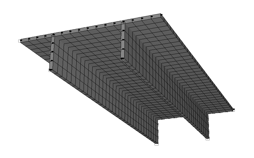
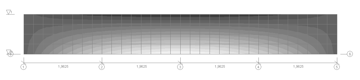
Design model
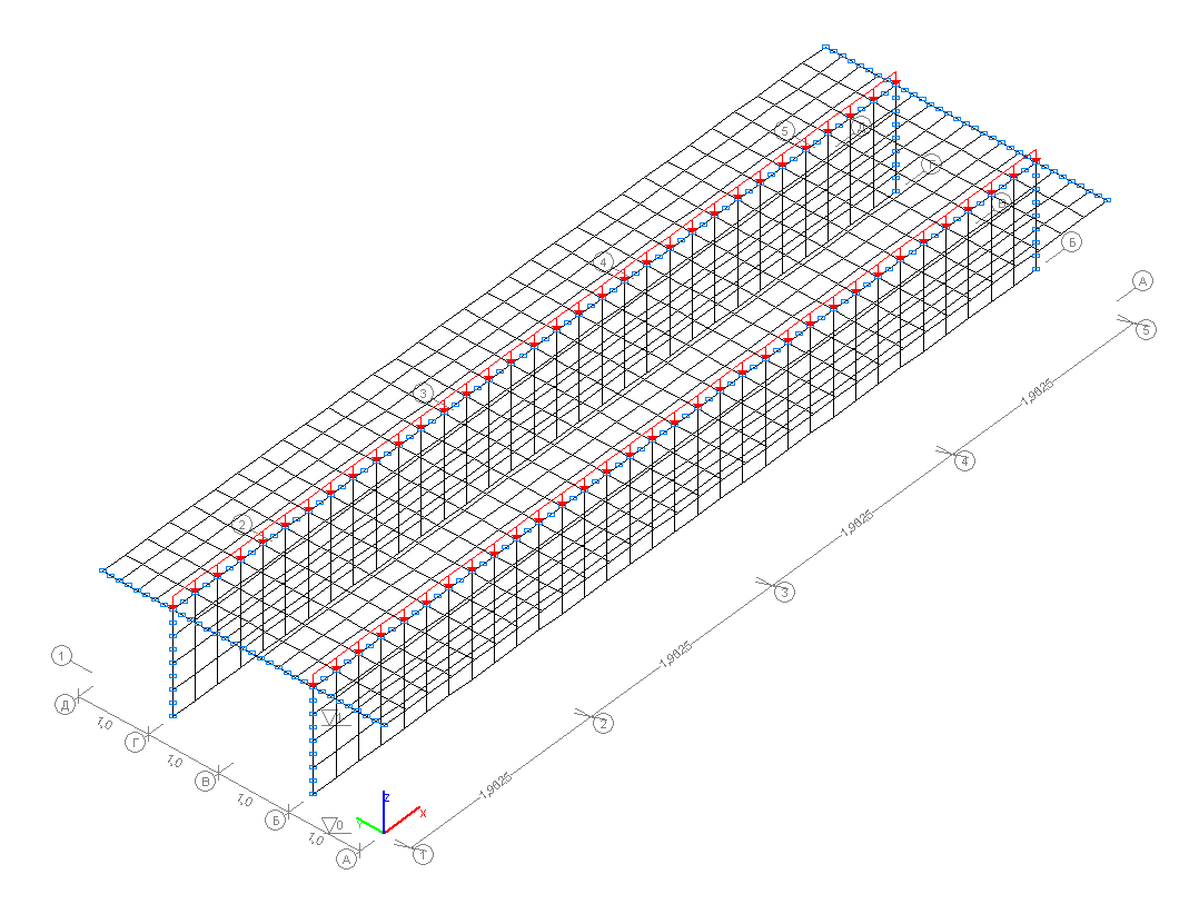
Design model
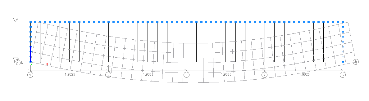
Deformed model
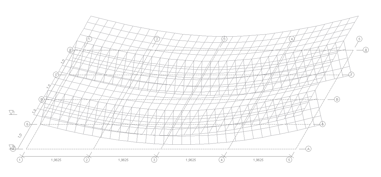
Deformed model
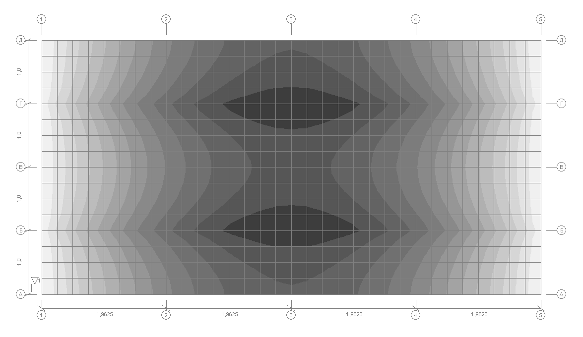
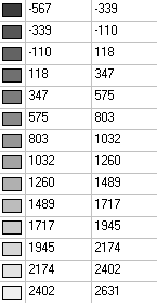
Values of the normal stresses in the beam flange σxi (kN/m2)
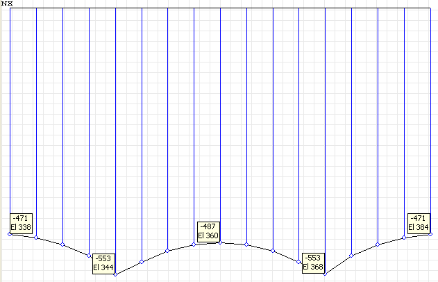
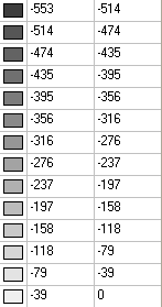
Diagram of the normal stresses in the beam flange σxi (kN/m2) for the cross-section in the middle of the grade beam span l/2
Diagram of the normal stresses in the beam flange σxi (kN/m2) for the cross-section in the quarter of the grade beam span l/4
Values of the normal stresses in the beam rib σxi (kN/m2)
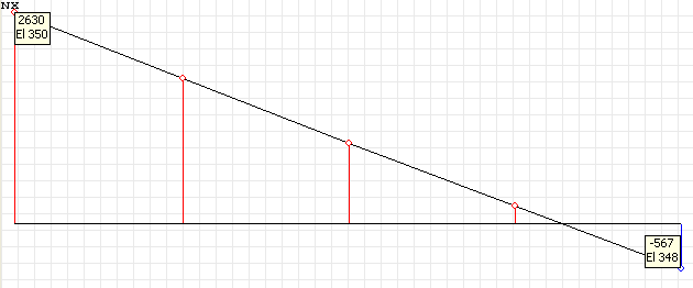
Diagram of the normal stresses in the beam rib σxi (kN/m2) for the cross-section in the middle of the grade beam span l/2
Diagram of the normal stresses in the beam rib σxi (kN/m2) for the cross-section in the quarter of the grade beam span l/4
Comparison of solutions:
Normal stresses σxi (kN/m2) acting along the beam in the elements of its structure in the points of the cross-section i = 1, 4, 5, 6 for the half (l/2) and quarter (l/4) of the beam span
|
x, m |
l/2 = 3.925 |
l/4 = 1.9625 |
||||||
|---|---|---|---|---|---|---|---|---|
|
i |
1 |
4 |
5 |
6 |
1 |
4 |
5 |
6 |
|
Theory |
-564 |
2631 |
-472 |
-488 |
-435 |
1987 |
-345 |
-359 |
|
SCAD |
-567 |
2631 |
-471 |
-487 |
-439 |
1989 |
-344 |
-358 |
|
Deviations, % |
0.53 |
0.00 |
0.21 |
0.20 |
0.92 |
0.10 |
0.29 |
0.28 |
Notes: In the analytical solution the normal stresses σxi (kN/m2), acting along the beam in the elements of its structure in the points of the cross-section i = 1, 4, 5, 6 for the half (l/2) and quarter (l/4) of the beam span taking into account seven harmonics of unknown generalized displacements for μ = 0.15 and l = 7.85∙b can be determined according to the following formulas (A. V. Aleksandrov, B. Ya. Lashchenikov, N. N. Shaposhnikov. Structural Mechanics. Thin-Walled Spatial Systems. — Moscow: Stroyizdat, 1983, p. 383):
\[ \sigma_{x1} \left( {l/2} \right)=-5.641\cdot \frac{q}{\delta }; \quad \sigma_{x4} \left( {l/2} \right)=26.305\cdot \frac{q}{\delta }; \quad \sigma_{x5} \left( {l/2} \right)=-4.718\cdot \frac{q}{\delta }; \quad \sigma_{x6} \left( {l/2} \right)=-4.881\cdot \frac{q}{\delta }; \] \[ \sigma_{x1} \left( {l/4} \right)=-4.349\cdot \frac{q}{\delta }; \quad \sigma_{x4} \left( {l/4} \right)=19.873\cdot \frac{q}{\delta }; \quad \sigma_{x5} \left( {l/4} \right)=-3.450\cdot \frac{q}{\delta }; \quad \sigma_{x6} \left( {l/4} \right)=-3.587\cdot \frac{q}{\delta }; \]