Thick Square Slab Simply Supported along the Sides Subjected to a Transverse Load Distributed over the Upper Face According to the Cosine Law

Objective: Determination of the stress-strain state of a thick square slab simply supported along the sides subjected to a transverse load distributed over the upper face according to the cosine law in accordance with the spatial problem of the theory of elasticity.
SCAD version used: 21.1
Initial data files:
|
File name |
Description |
|---|---|
|
Design model for the slab thickness of 4 m (γ = a / h = 3) |
Problem formulation: The thick square slab is simply supported along the sides and subjected to a transverse load distributed over the upper face according to the cosine law q·cos((π·x)/(2∙a))∙cos((π·y)/(2∙a)).
Determine:
- distribution of the horizontal normal stresses σx across the slab thickness z in its center
(x = 0, y = 0);
- distribution of the horizontal tangential stresses τxy across the slab thickness z on its lateral edge
(x = a, y = a);
- value of the vertical normal stresses σz in the center of the slab (x = 0, y = 0, z = 0);
- value of the vertical tangential stresses τxz in the center of the lateral face of the slab
(x = a, y = 0, z = 0);
- distribution of the vertical displacements z across the slab thickness z in its center (x = 0, y = 0);
- distribution of the horizontal displacements x across the slab thickness in the center of its lateral face
(x = a, y = 0, z = 0).
References: M.K. Usarov, The problem of bending the thick orthotropic plate of three-dimensional formulation, Magazine of Civil Engineering, 2011, No. 4, p. 40-47.
Initial data:
| E = 1.0·105 tf/m2 | - elastic modulus of the slab material; |
| υ = 0.3 | - Poisson’s ratio of the slab material; |
| 2∙a = 30.0 m | - side of the slab; |
| 2∙h = 10.0 m | - thickness of the slab; |
| q = 10.0 tf/m2 | - amplitude value of the transverse load distributed over the upper face of the slab according to the cosine law. |
Finite element model: Design model – general type system, plate elements – 72000 solid eight-node isoparametric elements of type 36. The spacing of the finite element mesh of the slab in plan and along the thickness is 0.5 m. Internal forces are output along the axes of the global coordinate system. Constraints of the linear degrees of freedom Y, Z are installed in the nodes of the lateral faces of the slab x = ± a. Constraints of the linear degrees of freedom X, Z are installed in the nodes of the lateral faces of the slab y = ± a b. Number of nodes in the design model – 78141.
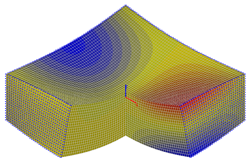
Results in SCAD
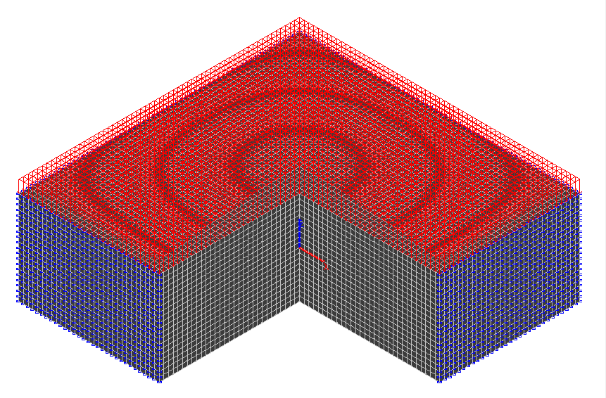
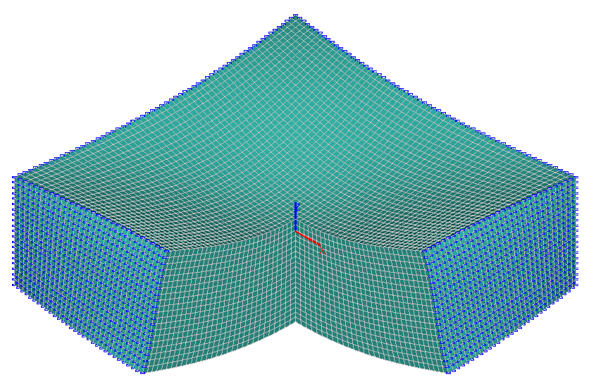
Design and deformed models
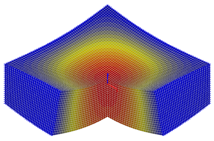
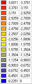
Values of vertical displacements z (mm)
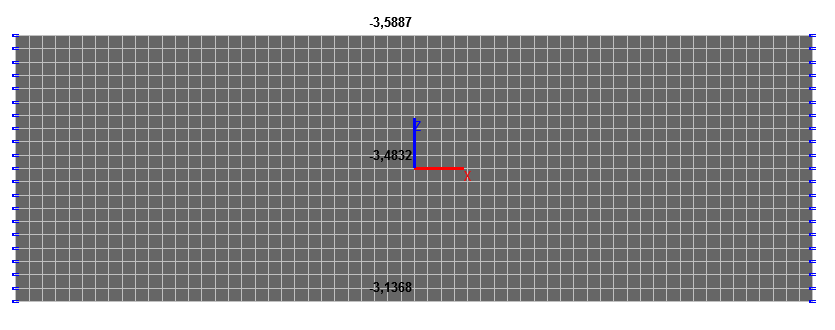
Values of vertical displacements z (mm) in the center of the slab (x = 0, y = 0)
Values of horizontal displacements x (mm)
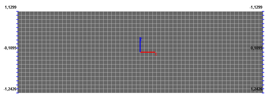
Values of horizontal displacements x (mm) in the middle of the lateral faces of the slab (x = ± a, y = 0, z = 0)
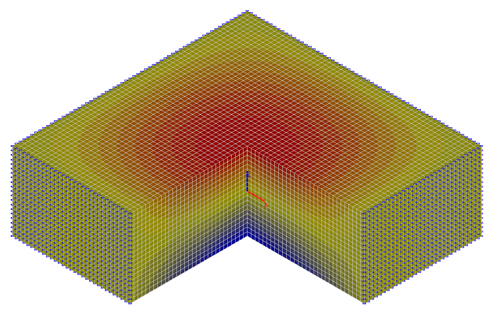
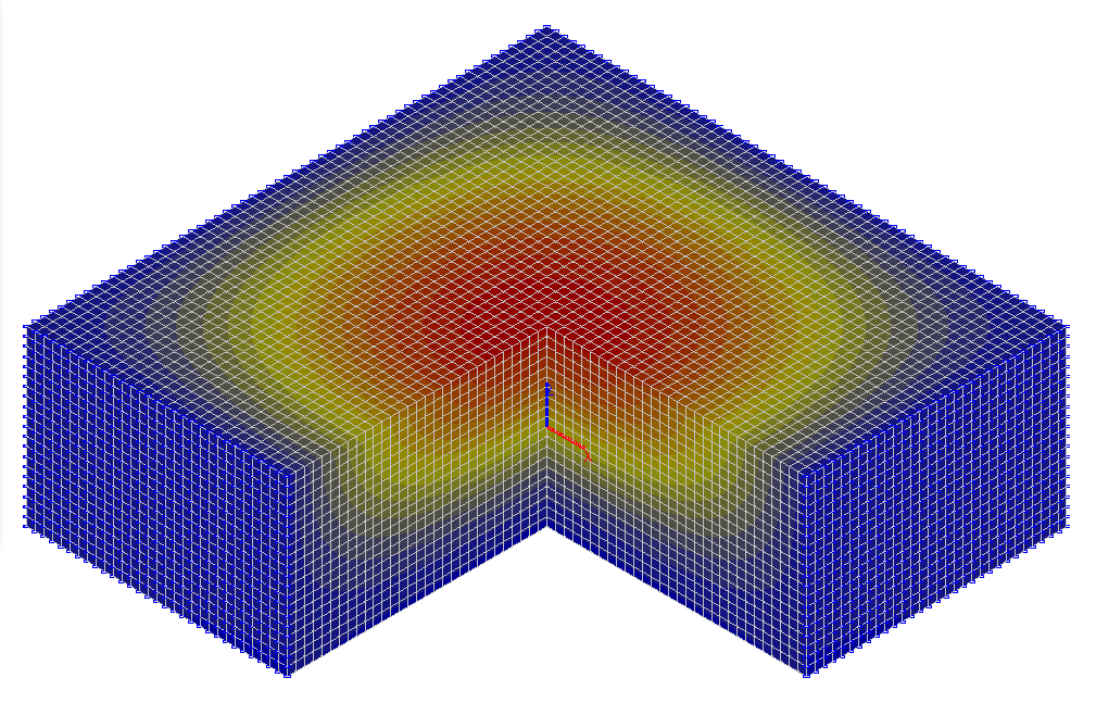
Values of horizontal normal stresses σx (tf/m2)
Values of horizontal tangential stresses τxy (tf/m2)
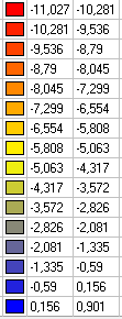
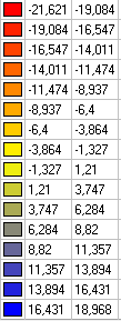
Values of vertical normal stresses σz (tf/m2)
Values of vertical tangential stresses τxz (tf/m2)
Comparison of solutions:
|
z / h |
σx , tf/m2 (x = y = 0) |
τxy , tf/m2 (x = y = a) |
||||
|---|---|---|---|---|---|---|
|
Theory |
SCAD |
Deviations, % |
Theory |
SCAD |
Deviations, % |
|
|
1.0 |
-21.240 |
-21.591 |
1.65 |
9.129 |
9.098 |
0.34 |
|
0.0 |
-0.481 |
-0.479 |
0.42 |
-0.882 |
-0.881 |
0.11 |
|
-1.0 |
18.639 |
18.942 |
1.63 |
-10.036 |
-10.005 |
0.31 |
|
z / h |
σz , tf/m2 (x = y = 0) |
τxz , tf/m2 (x = a, y = 0) |
||||
|---|---|---|---|---|---|---|
|
Theory |
SCAD |
Deviations, % |
Theory |
SCAD |
Deviations, % |
|
|
0.0 |
-4.944 |
-4.939 |
0.10 |
7.023 |
6.996 |
0.38 |
|
z / h |
z, mm (x = y = 0) |
x, mm (x = a, y = 0) |
||||
|---|---|---|---|---|---|---|
|
Theory |
SCAD |
Deviations, % |
Theory |
SCAD |
Deviations, % |
|
|
1.0 |
-3.5963 |
-3.5887 |
0.21 |
-1.1333 |
-1.1299 |
0.30 |
|
0.0 |
-3.4906 |
-3.4832 |
0.21 |
0.1095 |
0.1095 |
0.00 |
|
-1.0 |
-3.1440 |
-3.1368 |
0.23 |
1.2459 |
1.2426 |
0.26 |
Notes: In the analytical solution the horizontal normal stresses σx across the slab thickness z in its center (x = 0, y = 0), horizontal tangential stresses τxy across the slab thickness z on its lateral edge (x = a, y = a), vertical normal stresses σz in the center of the slab (x = 0, y = 0, z = 0), vertical tangential stresses τxz in the center of the lateral face of the slab (x = a, y = 0, z = 0), vertical displacements z across the slab thickness z in its center (x = 0, y = 0), horizontal displacements x across the slab thickness in the center of its lateral face (x = a, y = 0, z = 0) for υ = 0.3 and γ = a / h = 3 can be determined according to the following formulas:
\[ \frac{z}{h}=1.0: \quad \sigma_{x} =-2.1240\cdot q; \quad \tau_{xy} =-0.9129\cdot q; \quad \\ z=-3596.3\cdot \frac{q\cdot 2\cdot h}{E}; \quad x=-1133.3\cdot \frac{q\cdot 2\cdot h}{E}; \] \[ \frac{z}{h}=0.0: \quad \sigma_{x} =-0.0481\cdot q; \quad \tau_{xy} =-0.0882\cdot q \quad \sigma_{z} =-0.4944\cdot q; \quad \\ \tau_{xy} =0.7023\cdot q \quad z=-3490.6\cdot \frac{q\cdot 2\cdot h}{E}; \quad x=109.5\cdot \frac{q\cdot 2\cdot h}{E}; \] \[ \frac{z}{h}=-1.0: \quad \sigma_{x} =1.8639\cdot q; \quad \tau_{xy} =1.0036\cdot q; \quad z=-3144.0\cdot \frac{q\cdot 2\cdot h}{E}; \quad x=1245.9\cdot \frac{q\cdot 2\cdot h}{E}; \]