Stability of the System of Three Differently Loaded Columns of Different Rigidity Interconnected by Girders Infinitely Rigid in Bending

Objective: Determination of the critical values of the concentrated longitudinal forces with different values acting on the system of three columns of different rigidity interconnected by girders infinitely rigid in bending, corresponding to the moment of its buckling. Determination of the unsupported lengths of the columns.
Initial data file: frame_5b.spr
Problem formulation: Three columns of different rigidity embedded into the foundation and interconnected into a system by girders infinitely rigid in bending are subjected to the action of concentrated longitudinal forces with different values k∙N. The axial stiffness values of the girders and columns are assumed to be significant in order to exclude their effect on the solution of the problem. Determine the critical values of the concentrated longitudinal forces Ncr, corresponding to the moment of buckling of the system. Determine the unsupported lengths of the columns H0.
References: N. P. Melnikov, V. M. Vakhurkin, B. G. Lozhkin, Stability Analysis of Bar Systems. Reference data and examples, Moscow, Design Institute of Steel Structures, Issue 1395, 1954, p. 37.
Initial data:
| L = 5.0 m | - length of the girders of the frame; |
| H = 7.5 m | - height of the columns of the frame; |
| EA = 1.0·109 kN | - axial stiffness of the columns; |
| EIС1 = 1.14·105 kN∙m2 | - bending stiffness of the left column; |
| EIС2 = 2.28·105 kN∙m2 | - bending stiffness of the middle column; |
| EIС3 = 4.56·105 kN∙m2 | - bending stiffness of the right column; |
| 1∙N = 1.0·103 kN | - initial value of the concentrated longitudinal force on the left column; |
| 2∙N = 2.0·103 kN | - initial value of the concentrated longitudinal force on the middle column; |
| 3∙N = 3.0·103 kN | - initial value of the concentrated longitudinal force on the right column. |
Finite element model: Design model – plane frame, columns – 45 elements of type 2 (the spacing of the finite element mesh along the longitudinal axes is 0.5 m), girders – 2 elements of type 100 (three-node rigid bodies with the constraints in the directions X, Z and UY, master nodes in the middle of the girder spans, and slave nodes on the connected columns). Boundary conditions are provided by imposing constraints on the support nodes of the columns in the directions of the degrees of freedom X, Z, UY. The action with the initial values of the concentrated longitudinal forces k∙N is specified in the beam-to-column joints. Number of nodes in the design model – 50.
Results in SCAD
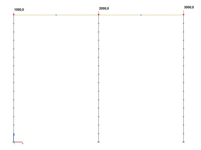
Design model
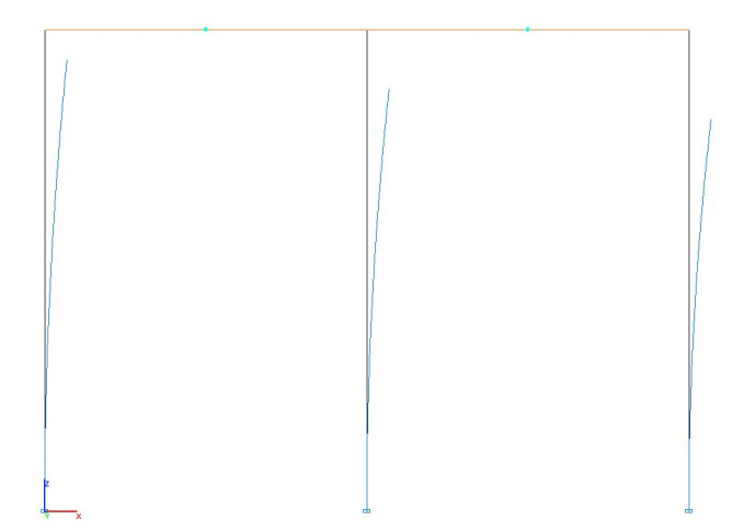
Buckling mode
Comparison of solutions:
|
Parameter |
Theory |
SCAD |
Deviation, % |
|---|---|---|---|
|
Critical value of the concentrated longitudinal force on the left column (С1) Ncr, kN |
2332.8 (2333.6) |
2.332764∙1000 = = 2332.7 |
0.00 (0.04) |
|
Critical value of the concentrated longitudinal force on the middle column (С2) Ncr, kN |
4665.6 (4667.2) |
2.332764∙2000 = = 4665.5 |
0.00 (0.04) |
|
Critical value of the concentrated longitudinal force on the right column (С3) Ncr, kN |
6998.5 (7000.8) |
2.332764∙3000 = = 6998.3 |
0.00 (0.04) |
|
Unsupported length of the left column (С1) H0, m |
6.9448 (6.9437) |
6.9449 |
0.00 (0.02) |
|
Unsupported length of the middle column (С2) H0, m |
6.9448 (6.9437) |
6.9449 |
0.00 (0.02) |
|
Unsupported length of the right column (С3) H0, m |
8.0192 (8.0178) |
8.0193 |
0.00 (0.02) |
The values of the approximate solution by the equivalent frame method are given in brackets
Notes: In the exact analytical solution the critical values of the concentrated longitudinal forces Ncr, corresponding to the moment of buckling of the system, and the unsupported lengths of the columns H0 can be determined according to the following formulas:
\[ {\begin{array}{*{20}c} {С1:} & {N_{cr} =\nu^{2}\cdot \frac{EI_{С1} }{H^{2}}} & {С2:} & {N_{cr} =2\cdot \nu^{2}\cdot \frac{EI_{С1} }{H^{2}}} & {С3:} & {3\cdot \nu^{2}\cdot \frac{EI_{С1} }{H^{2}}} \\ \end{array} }, \]
where ν (critical load parameter) is determined by solving the transcendental equation:
\[ 6\cdot \nu \cdot \left( {\frac{tg\left( {\frac{\nu }{2}} \right)}{2\cdot tg\left( {\frac{\nu }{2}} \right)-\nu }+\frac{2\cdot tg\left( {\frac{\sqrt {3\cdot } \nu }{4}} \right)}{4\cdot tg\left( {\frac{\sqrt {3\cdot } \nu }{4}} \right)-\sqrt {3\cdot } \nu }} \right)=0; \] \[ {\begin{array}{*{20}c} {С1:} & {H_{0} =\frac{\pi \cdot H}{\nu };} & {С2:} & {H_{0} =\frac{\pi \cdot H}{\nu };} & {С3:} & {H_{0} =\frac{2}{\sqrt 3 }\cdot \frac{\pi \cdot H}{\nu }.} \\ \end{array} } \]
In the approximate analytical solution the critical value of the concentrated longitudinal forces Ncr, corresponding to the moment of buckling of the system, and the unsupported lengths of the columns H0 can be determined according to the following formulas:
\[ {\begin{array}{*{20}c} {С1:} & {N_{cr} =\frac{7}{6}\cdot \frac{\pi^{2}\cdot EI_{С1} }{H^{2}}} & {С2:} & {N_{cr} =\frac{7}{3}\cdot \frac{\pi ^{2}\cdot EI_{С1} }{H^{2}}} & {С3:} & {N_{cr} =\frac{7}{2}\cdot \frac{\pi^{2}\cdot EI_{С1} }{H^{2}}} \\ \end{array} }; \] \[ {\begin{array}{*{20}c} {С1:} & {H_{0} =\sqrt {\frac{6}{7}} \cdot H} & {С2:} & {H_{0} =\sqrt {\frac{6}{7}} \cdot H} & {С3:} & {H_{0} =\sqrt {\frac{8}{7}} \cdot H.} \\ \end{array} } \]