Stability of In-Plane Bending of a Cantilever Strip of a Rectangular Cross-Section by a Shear Force Applied at the Free End

Objective: Determination of the critical value of the concentrated shear force applied at the free end of a cantilever strip of a rectangular cross-section corresponding to the moment of its buckling.
Initial data files:
|
File name |
Description |
|
Thickness of the cantilever strip cross-section – 0.01 m |
|
|
Thickness of the cantilever strip cross-section – 0.10 m |
|
|
Thickness of the cantilever strip cross-section – 1.00 m |
Problem formulation: The cantilever strip of a rectangular cross-section is subjected to the action of the concentrated shear force P, applied at its free end. Determine the critical value of the concentrated shear force Pcr, corresponding to the moment of buckling of the cantilever strip.
References: S. P. Timoshenko, Stability of Bars, Plates and Shells. — Moscow. — Nauka. — 1971. — p. 291.
A.S. Volmir. Stability of Deformable Systems. — Moscow. — Nauka. — 1967. — p.211;
A. V. Perelmuter, V. I. Slivker, Handbook of Mechanical Stability in Engineering. — Volume 1. — Moscow. — SCAD SOFT. — 2010. — p. 465;
A. V. Perelmuter, V. I. Slivker, Handbook of Mechanical Stability in Engineering. — Volume 2. — Moscow. — SCAD SOFT. — 2010. — p. 17.
Initial data:
| L = 10.0 m | - length of the cantilever strip; |
| h = 1.0 m | - height of the cantilever strip cross-section; |
| b = 0.01; 0.10; 1.00 m | - thickness of the cantilever strip cross-section; |
| E = 3.0·107 kN/m2 | - elastic modulus of the cantilever strip material; |
| ν = 0.2 | - Poisson’s ratio; |
| P1 = 1.0; 1.0·103; 1.0·105 kN | - initial value of the concentrated shear force applied at the free end in the plane of the strip; |
| P = 1.0; 1.0·103; 1.0·105 kN | - initial value of the concentrated shear force applied at the free end out of the plane of the strip. |
Finite element model: Design model – general type system. Reissner-Mindlin shell element model, 2560 eight-node elements of type 150, the spacing of the finite element mesh along the longitudinal axis and along the height of the strip is 0.0625 m. Boundary conditions are provided by imposing constraints on the nodes of the clamped end of the strip in the directions of the degrees of freedom X, Y, Z, UX, UY, UZ. The action with the initial value of the concentrated shear force P is specified in the node of the longitudinal axis of the strip on the free end. Number of nodes in the design model – 8033.
The stability of in-plane bending of the cantilever strip subjected to the shear force applied at the free end in the plane of the strip is checked.
Results in SCAD
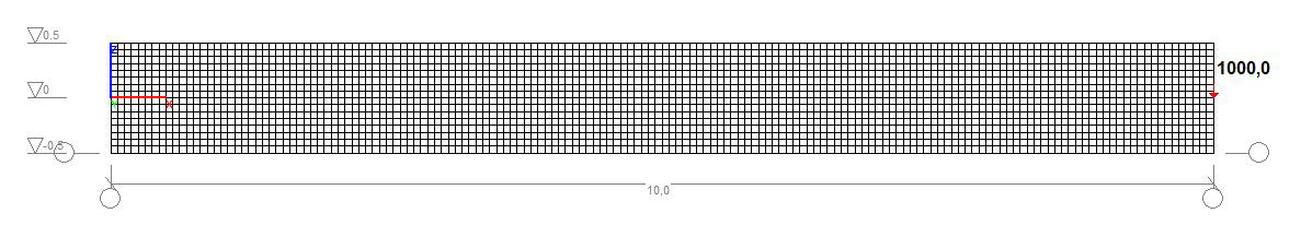
Design model. Reissner-Mindlin shell element model
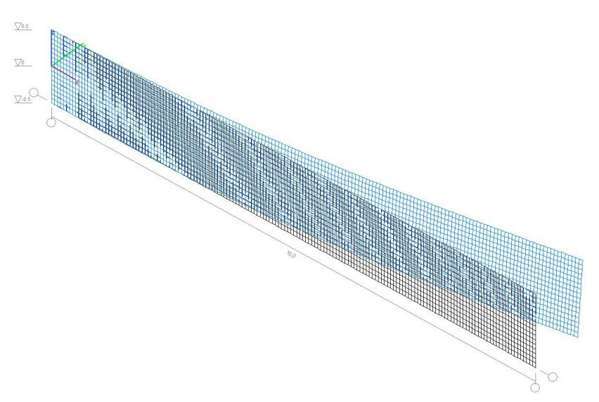
Buckling mode. Reissner-Mindlin shell element model
Comparison of solutions:
The critical value of the concentrated shear force P1cr (kN),
applied at the free end in the plane of the strip
|
Design model |
Theory |
SCAD |
Deviation, % |
|
|---|---|---|---|---|
|
Reissner-Mindlin shell element |
b = 0.01 m |
0.12901 (0.12901) |
0.134811∙1 = 0.13481 |
4.50 (4.50) |
|
b = 0.10 m |
125.28 (124.66) |
0.130559∙1000 = 130.56 |
4.21 (4.73) |
|
|
b = 1.00 m |
84048 (59431) |
0.821978∙100000 = 82198 |
2.20 (38.31) |
|
Theoretical values calculated taking into account the effect of the bending stiffness in the shear force plane are given in brackets
Notes: In the analytical solution the critical value of the concentrated shear force Pcr, corresponding to the moment of buckling of the cantilever strip can be determined according to the following formulas:
\[ P_{cr} =\frac{4.01}{l^{2}}\cdot \sqrt {B\cdot C} \]
without taking into account the effect of the bending stiffness in the shear force plane
\[P_{cr} =\frac{4.01}{l^{2}}\cdot \sqrt {\frac{B\cdot C\cdot B_{1} }{B+B_{1} }} =\frac{k}{l^{2}}\cdot \sqrt {B\cdot C} , \] \[ where: \quad k=\frac{4.01}{\sqrt {1+\left( {\frac{b}{h}} \right)^{2}} }. \]
taking into account the effect of the bending stiffness in the shear force plane
\(B=E\cdot \frac{h\cdot b^{3}}{12} \) – minimum bending stiffness (out of the moment plane);
\( B_{1} =E\cdot \frac{b\cdot h^{3}}{12} \) – maximum bending stiffness (in the moment plane);
\( C=\frac{E}{2\cdot \left( {1+\nu } \right)}\cdot k_{f} \cdot h\cdot b^{3} \) – free torsional stiffness, where:
\[ k_{f} =\frac{1}{3}\cdot \left\{ {1-\frac{192}{\pi^{5}}\cdot \frac{b}{h}\cdot \sum\limits_{n=1}^\infty {\left[ {\sin^{2}\left( {\frac{n\cdot \pi }{2}} \right)\cdot \frac{1}{n^{5}}\cdot th\left( {\frac{n\cdot \pi \cdot h}{2\cdot b}} \right)} \right]} } \right\}. \]