Stability of a Simply Supported Square Plate Uniformly Compressed in One Direction under Kinematic Action

Objective: Determination of the critical value of the approach of two opposite sides of a simply supported square plate corresponding to the moment of its buckling.
Initial data files:
|
File name |
Description |
|---|---|
|
Design model with four-node shell elements of type 44 |
|
|
Design model with eight-node shell elements of type 50 |
Problem formulation: The square plate is subjected to the action of the approach Δ of two opposite roller supported sides. Two other opposite sides of the plate free from actions are pinned. Determine the critical value of the approach Δcr, corresponding to the moment of buckling of the square plate.
References: J.H. Argyris, P.C. Dunne, G.A. Malejannakis, E. Schelkle, A simple triangular facet shell element with applications to linear and non-linear equilibrium and elastic stability problems, Computer methods in applied mechanics and engineering, 11 (1977), p. 97-131.
S.P. Timoshenko, J.M. Gere, Theory of elastic stability, McGraw-Hill, New York, 1963, p. 356.
Initial data:
| a = 8.0 m | - side of the square plate; |
| h = 0.08 m | - thickness of the square plate; |
| E = 1.0·107 kN/m2 | - elastic modulus of the square plate material; |
| ν = 1/3 | - Poisson’s ratio; |
| Δ = 1.0·10-3 m | - initial value of the approach. |
Finite element model: Design model – general type system. Two design models with four-node shell elements of type 44 and eight-node shell elements of type 50 are considered. The spacing of the finite element mesh along the sides of the plate (along the X and Y axes of the global coordinate system) is 1.0 m. Number of elements in the models – 64. Boundary conditions are provided by imposing constraints on the nodes of the support contour of the plate in the direction of the degree of freedom Z, and by imposing constraints in the normal direction along the Y axis of the global coordinate system on the nodes of one of the two opposite sides of the plate free from actions. Constraints in the respective direction (along the X axis of the global coordinate system) are imposed on the nodes of two opposite sides of the plate subjected to the kinematic action. The action is specified by the displacement of the constraints of one of these sides with the initial value Δ = 1.0·10-3 m. The dimensional stability of the design model is provided by imposing a constraint in the UZ direction of the global coordinate system on the node of the support contour of the plate. Number of nodes in the models – 81; 225.
Results in SCAD
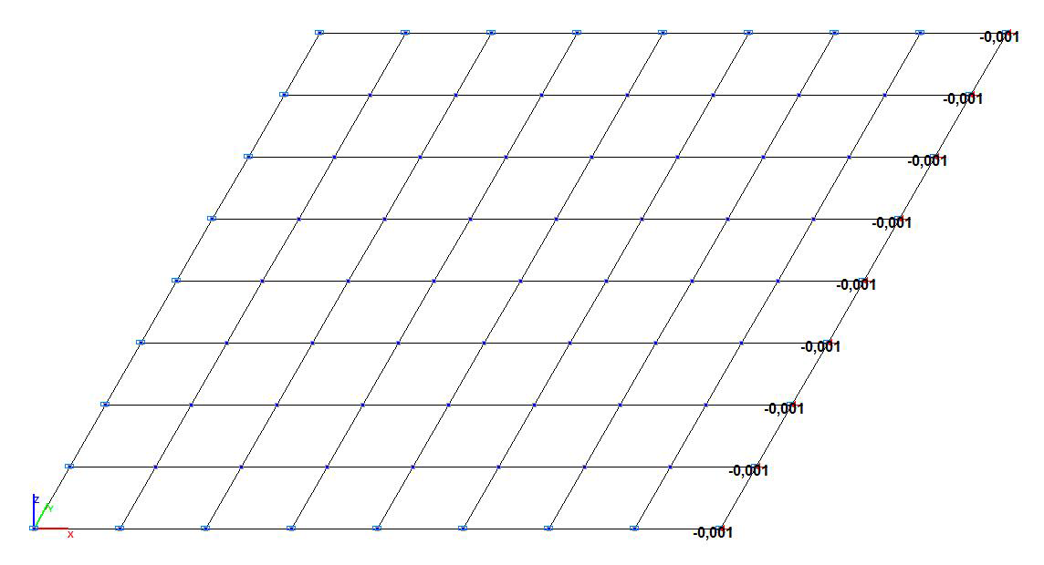
Design model. Model with four-node shell elements
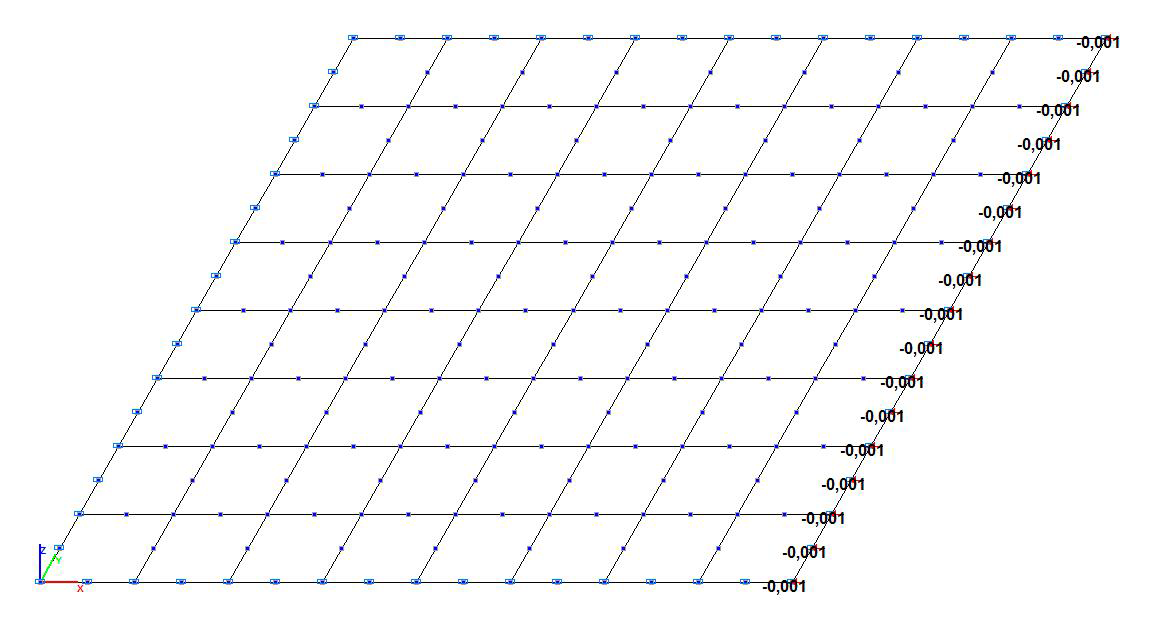
Design model. Model with eight-node shell elements
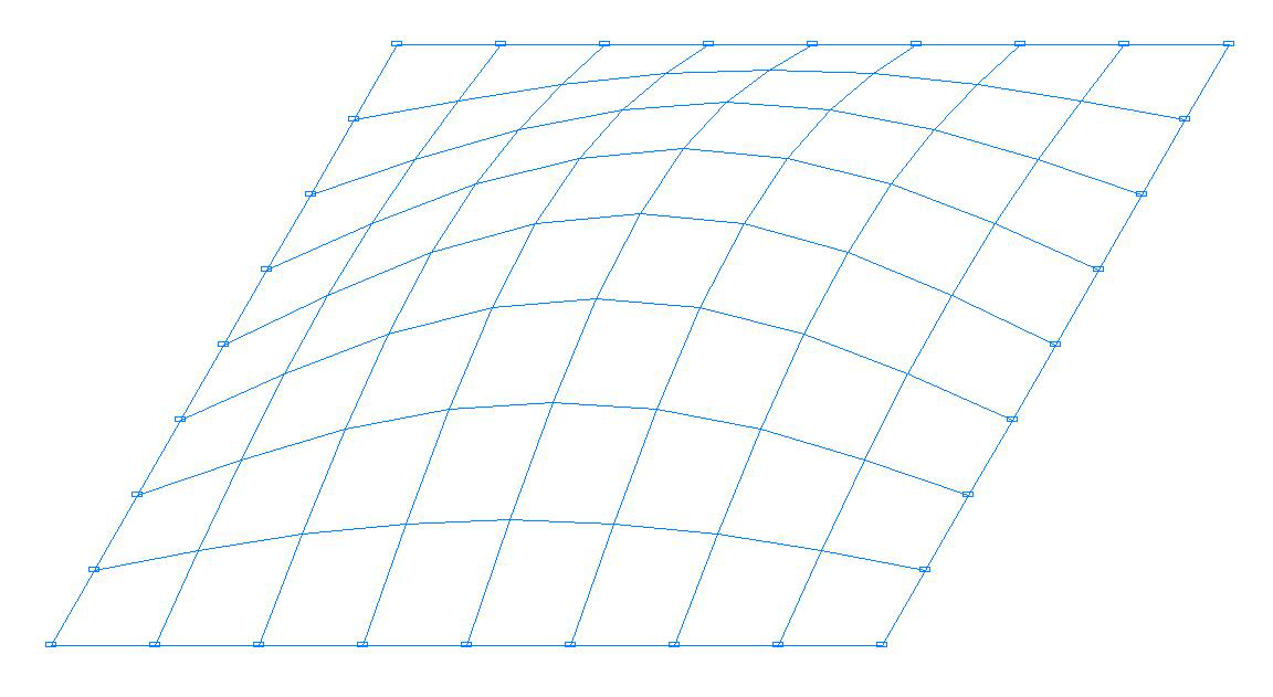
Buckling mode. Model with four-node shell elements
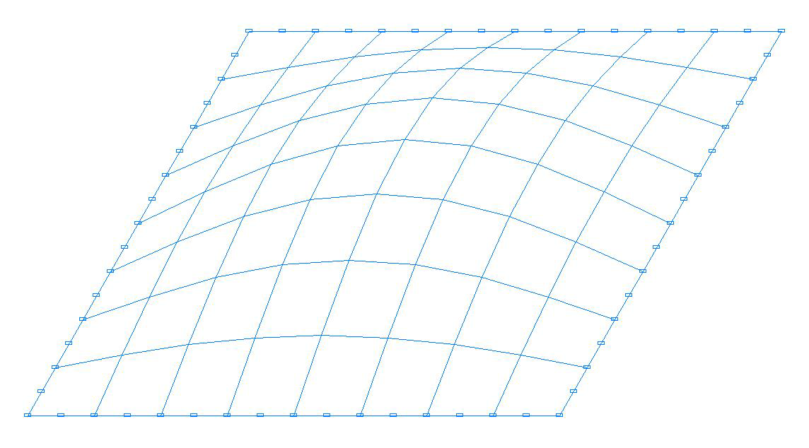
Buckling mode. Model with eight-node shell elements
Comparison of solutions:
Critical value of the compressive forces σcr, kN/m2
|
Design model |
Theory |
SCAD |
Deviation, % |
|---|---|---|---|
|
Member type 44 n = 4 nodes |
1.974∙10-3 |
1.999043∙1.0∙10-3 = = 1.999∙10-3 |
1.27 |
|
Member type 50 n = 8 nodes |
1.973935∙1.0∙10-3 = = 1.974∙10-3 |
0.00 |
Notes: In the analytical solution the critical value of the approach Δcr of two opposite sides of the simply supported square plate corresponding to the moment of its buckling can be determined according to the following formula:
\[ \Delta_{cr} =\frac{\pi^{2}\cdot h^{2}}{3\cdot \left( {1+\nu } \right)\cdot a}. \]