Vertical Cantilever Bar of Square Cross-Section with Longitudinal and Transverse Concentrated Loads at Its Free End

Objective: Check of the consistency of the results for models of different dimensions.
Initial data files:
| File name | Description |
|---|---|
| 4.9_c.spr | Bar model |
| 4.9_p.spr | Shell element model |
| 4.9_o.spr | Solid element model |
Problem formulation: Determine the displacements of the free end x, y, z and maximum stresses in the clamped section σz.
Initial data:
| E = 3.0·107 kPa | - elastic modulus; |
| μ = 0.2 | - Poisson’s ratio; |
| b = h = 0.5 m | - cross-sectional dimensions of the cantilever bar; |
| l = 10 m | - height of the cantilever bar; |
| Px = 10 kN | - value of the concentrated force acting along the X axis of the global coordinate system ( loading 1 ); |
| Py = 10 kN | - value of the concentrated force acting along the Y axis of the global coordinate system ( loading 2 ); |
| N = 10000 kN | - value of the concentrated force acting along the Z axis of the global coordinate system ( loading 3 ). |
Finite element model: Design model – general type system. Three design models are considered:
Bar model (B), 2 elements of type 5, 3 nodes;
Shell element model (P), 20 elements of type 50, 85 nodes;
Solid element model (S), 10 elements of type 37, 128 nodes.
Results in SCAD
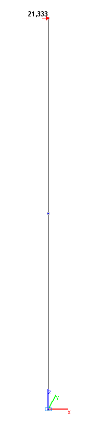
Values of the displacements x, y , z in the bar model (mm)
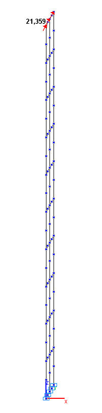
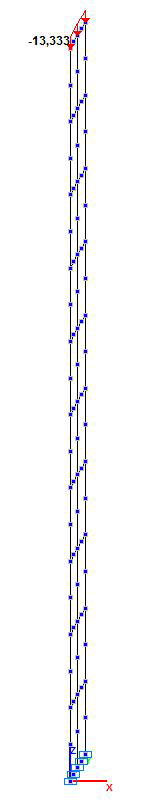
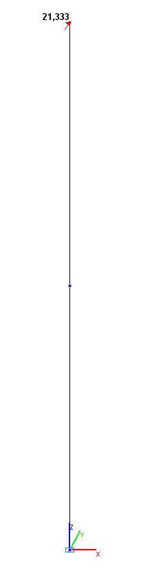
Values of the displacements x, y , z in the shell element model (mm)
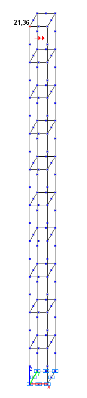
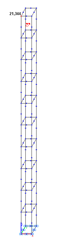
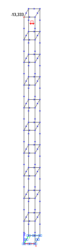
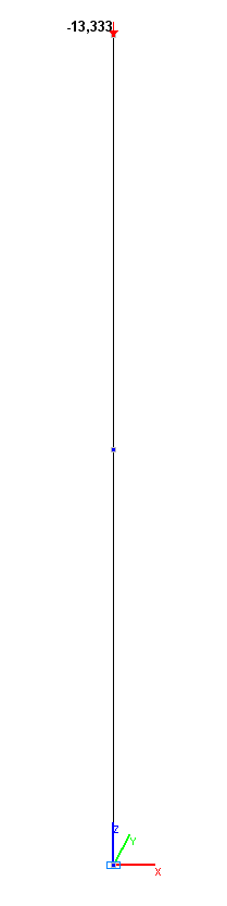
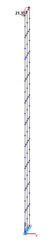
Values of the displacements x, y , z in the solid element model (mm)
Comparison of solutions:
|
Model |
Loading 1 |
|||
|---|---|---|---|---|
|
Displacements x (mm) |
Deviations, % |
Stresses σz (kPa) |
Deviations, % |
|
|
Bar (B) |
21.333 |
0.00 |
4800 |
0.00 |
|
Shell element (P) |
21.330 |
0.01 |
4819 |
0.40 |
|
Solid element (S) |
21.336 |
0.01 |
4738 |
1.29 |
|
Theory |
21.333 |
─ |
4800 |
─ |
|
Model |
Loading 2 |
|||
|---|---|---|---|---|
|
Displacements y (mm) |
Deviations, % |
Stresses σz (kPa) |
Deviations, % |
|
|
Bar (B) |
21.333 |
0.00 |
4800 |
0.00 |
|
Shell element (P) |
21.359 |
0.12 |
4720 |
1.67 |
|
Solid element (S) |
21.345 |
0.06 |
4743 |
1.19 |
|
Theory |
21.333 |
─ |
4800 |
─ |
|
Model |
Loading 3 |
|||
|---|---|---|---|---|
|
Displacements z (mm) |
Deviations, % |
Stresses σz (kPa) |
Deviations, % |
|
|
Bar (B) |
-13.333 |
0.00 |
-40000 |
0.00 |
|
Shell element (P) |
-13.333 |
0.00 |
-40000 |
0.00 |
|
Solid element (S) |
-13.333 |
0.00 |
-40000 |
0.00 |
|
Theory |
-13.333 |
─ |
-40000 |
─ |
Notes: In the analytical solution for non-deformed models, the displacements of the free end x, y, z and the maximum stresses in the clamped section σz are determined according to the following formulas:
\[ x=\frac{4\cdot Px\cdot l^{3}}{E\cdot b\cdot h^{3}}; \quad y=\frac{4\cdot Py\cdot l^{3}}{E\cdot h\cdot b^{3}}; \quad z=\frac{N\cdot l}{E\cdot b\cdot h}; \] \[ \sigma_{z} \left( {Px} \right)=\frac{6\cdot Px\cdot l}{b\cdot h^{2}}; \quad \sigma_{z} \left( {Py} \right)=\frac{6\cdot Py\cdot l}{h\cdot b^{2}}; \quad \sigma_{z} \left( N \right)=\frac{N}{b\cdot h}. \]