Flexible Long Rectangular Plate Simply Supported along the Longitudinal Edges Subjected to a Uniformly Distributed Transverse Load

Objective: Determination of the stress-strain state of a flexible long rectangular plate simply supported along the longitudinal edges subjected to a uniformly distributed transverse load.
Initial data file: nel.spr
Problem formulation: The flexible long rectangular plate simply supported along the longitudinal edges is subjected to the transverse load q uniformly distributed over its area. Determine the transverse displacement Z of the deformed midsurface, as well as the maximum syd and minimum syt normal stresses over the cross-section in the half of the plate span.
References: S. Timoshenko, S. Woinowsky-Krieger, Theory of Plates and Shells, Moscow, Fizmatgis, 1963, p. 20.
Initial data:
| E = 2.1·106 kgf/cm2 | - elastic modulus; |
| ν = 0.3 | - Poisson’s ratio; |
| h = 1.3 cm | - thickness of the plate; |
| l = 130.0 cm | - short side of the plate (along the Y axis of the global coordinate system); |
| b = 260.0 cm | - size of the elementary strip of the long side of the plate (along the X axis of the global coordinate system); |
| q = 1.4 kgf/cm2 | - value of the uniformly distributed transverse load. |
Finite element model: Design model – general type system, 1352 plate elements of type 341. The spacing of the finite element mesh along the sides of the plate (along the X, Y axes of the global coordinate system) is 5.0 cm. Boundary conditions are provided by imposing constraints in the directions of the degrees of freedom X, Y, Z for the long edges parallel to the X axis of the global coordinate system based on the simply supported conditions, and in the directions of the degrees of freedom X, UY for the short edges parallel to the Y axis of the global coordinate system based on the conditions of cylindrical bending of the elementary strip of the long side of the plate. Number of nodes in the design model 1431. The calculation is performed in the geometrically nonlinear formulation by the incremental-iterative method with the following parameters: loading factor – 0.1, number of steps – 10, . number of iterations – 30.
Results in SCAD
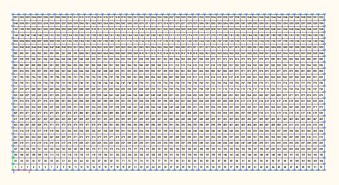
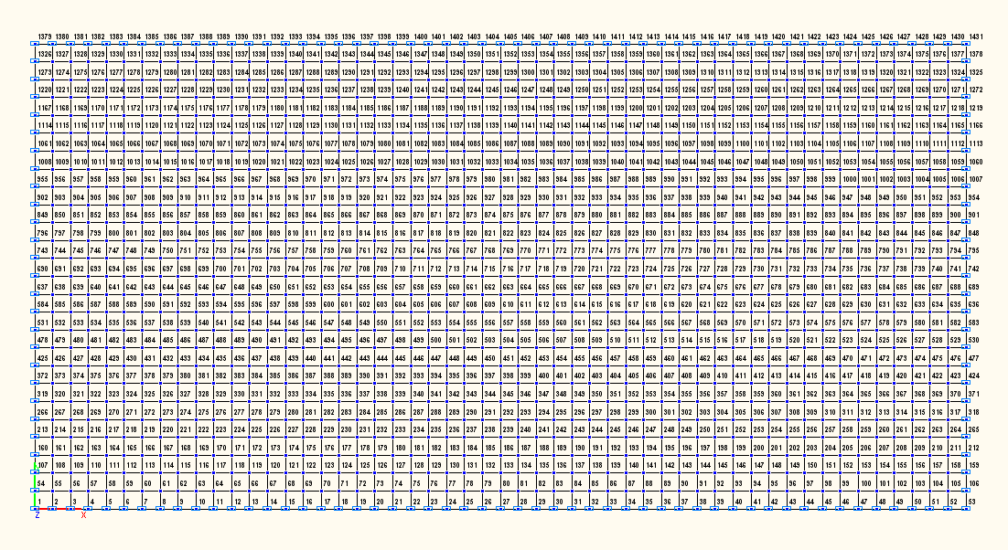
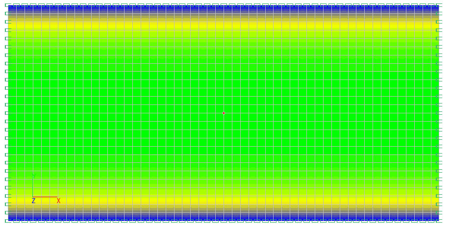
Design model
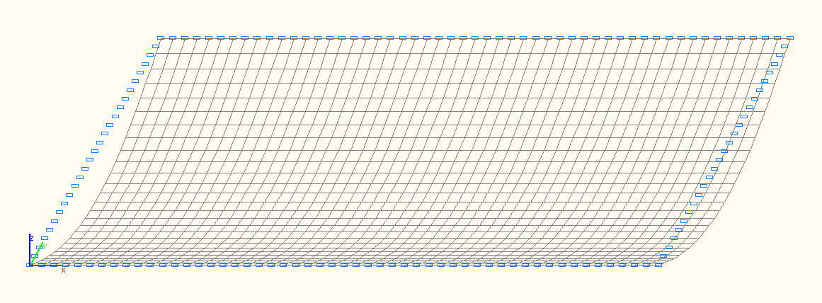
Deformed model
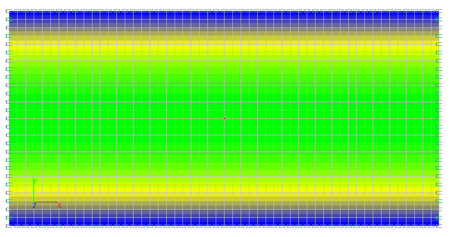
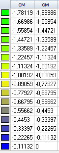
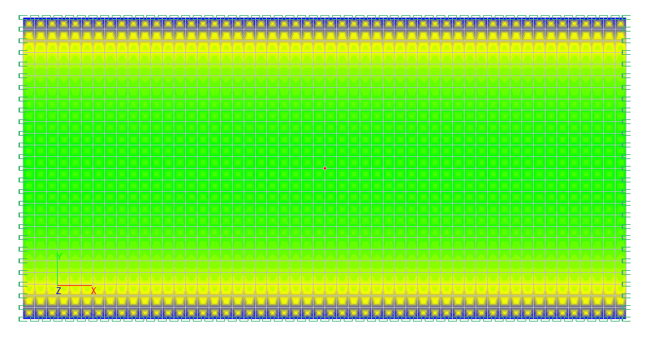
Values of transverse displacements Z (cm)
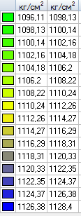
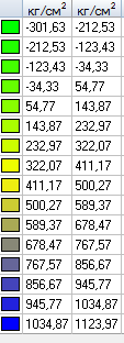
Values of longitudinal stresses Ny (kgf/cm2)
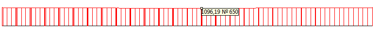
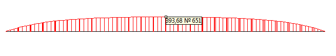
Longitudinal stress diagram Ny (kgf/cm2)
Values of bending moments My (kgf·cm/cm)
Bending moment diagram My (kgf·cm/cm)
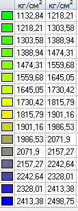
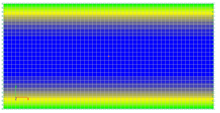
Values of normal stresses syd (kgf/cm2)
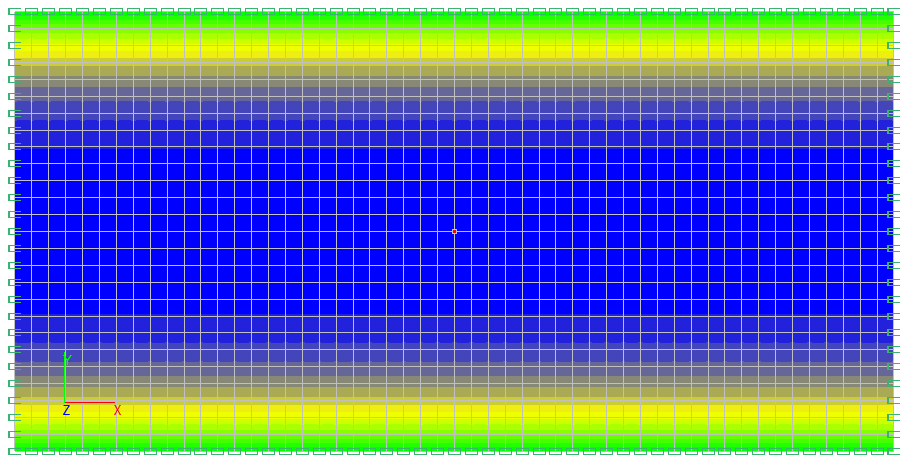
Values of normal stresses syt (kgf/cm2)
Comparison of solutions:
|
Parameter |
Theory |
SCAD |
Deviations, % |
|---|---|---|---|
|
Transverse displacement Z of the deformed midsurface in the half of the plate span, cm |
-1.782 |
-1.781 |
0.06 |
|
maximum normal stresses over the cross-section in the half of the plate span syd, kgf/cm2 |
2503 |
2498.7 |
0,17 |
|
minimum normal stresses over the cross-section in the half of the plate span syt, kgf/cm2 |
-287 |
-294.0 |
2.44 |
Notes: In the analytical solution the displacement Z of the deformed midsurface, as well as the maximum syd and minimum syt normal stresses over the cross-section in the half of the plate span can be calculated according to the following formulas:
\[ Z=\frac{5\cdot q\cdot l^{4}}{384\cdot D}\cdot \frac{\frac{1}{ch(u)}-1+\frac{u^{2}}{2}}{\frac{5\cdot u^{4}}{24}}; \quad s_{yd} =s_{yN} +s_{yM} ; \quad s_{yt} =s_{yN} -s_{yM} , \] \[ where: \quad s_{yN} =\frac{N_{y} }{h}; \quad s_{yM} =\frac{6\cdot M_{y} }{h^{2}}; \quad N_{y} =\frac{4\cdot u^{2}\cdot D}{l^{2}}; \quad M_{y} =\frac{q\cdot l^{2}}{8}\cdot \frac{1-\frac{1}{ch(u)}}{\frac{u^{2}}{2}}; \quad D=\frac{E\cdot h^{3}}{12\cdot \left( {1-\nu^{2}} \right)}. \]
The value \( u \) is determined from the following expression: \( \frac{E^{2}\cdot h^{8}}{\left( {1-\nu^{2}} \right)^{2}\cdot q^{2}\cdot l^{8}}=\frac{135}{16}\cdot \frac{th(u)}{u^{9}}+\frac{27}{16}\cdot \frac{th^{2}(u)}{u^{8}}-\frac{135}{16\cdot u^{8}}+\frac{9}{8\cdot u^{6}}. \)