Three-Span Beam with One Clamped End and Three Rigid One-Sided Supports Subjected to Concentrated Forces above Them


Objective: Determination of the reactions of one-sided supports of a three-span beam or deflections of the beam in the direction of installation of the supports in the structurally nonlinear formulation.
Initial data file: Contact_1.spr
Problem formulation: The three-span beam with one clamped end and three rigid one-sided supports working in compression is subjected to concentrated shear forces above them.
Determine the reactions of the one-sided supports Ri or the deflections of the beam Zi in the direction of installation of the supports.
References: A.V. Perelmuter, V.I. Slivker, Design Models of Structures and a Possibility of Their Analysis, Moscow, SCAD SOFT, 2011, p. 146
Initial data:
| EF = 1.00·108 kN | - axial stiffness of the beam cross-section; |
| EI = 44.50 kN∙m2 | - bending stiffness of the beam cross-section; |
| L = 2.00 m | - beam span length; |
| k = 1.00·106 kN/m | - axial stiffness of the one-sided supportsр; |
| P1 = 0.7071 kN | - value of the concentrated force applied above the first (from the clamping) intermediate one-sided support and stretching it; |
| P2 = 4.3597 kN | - value of the concentrated force applied above the second (from the clamping) intermediate one-sided support and stretching it; |
| P3 = 2.1155 kN | - value of the concentrated force applied above the third (from the clamping) end one-sided support and compressing it. |
Finite element model: Design model – plane frame. Elements of the beam – 24 bar elements of type 2. The spacing of the finite element mesh along the beam length (along the X1 axes of the local coordinate systems) is 0.25 m. Elements of the one-sided supports – 3 two-node elements of unilateral constraints of type 352. Boundary conditions are provided by imposing constraints on the support node of the clamped end of the beam in the directions of the degrees of freedom X, Z, UY and on the support nodes of the one-sided supports in the directions of the degrees of freedom X, Z. The actions are specified as transverse nodal loads P (in the direction of the Z axis of the global coordinate system). The nonlinear loading was generated for the incremental-iterative method with a loading factor - 1, number of steps - 1, number of iterations - 10 for the linear loading P. Number of nodes in the design model – 28.
Results in SCAD
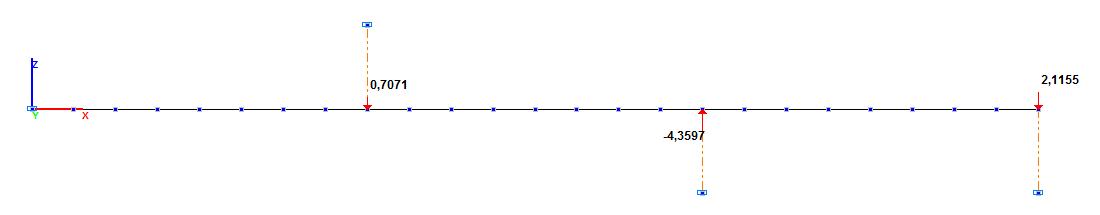
Design model
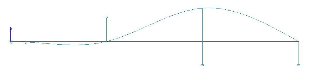
Deformed model
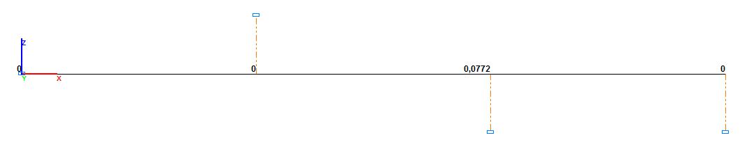
Values of deflections of the beam Zi, m
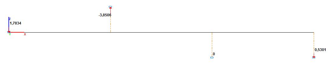
Values of reactions of the one-sided supports, kN
Comparison of solutions:
|
Parameter |
Theory |
SCAD |
Deviation, % |
|---|---|---|---|
|
R1, kN |
3.7872 |
3.8506 |
1.67 |
|
R3, kN |
0.5302 |
0.5301 |
0.02 |
|
Z2, m |
0.0772 |
0.0772 |
0.00 |
Notes: In the analytical solution the reactions of the one-sided supports Ri or the deflections of the beam Zi in the direction of installation of the supports are determined by the quadratic programming method.