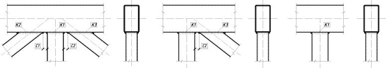
(a)
(b)
(c)
(d) (g)
(f)
(g)
(h)
(i)
(k)
(l)
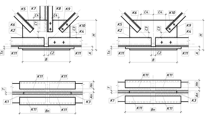
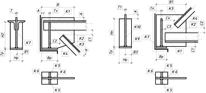
Figure 1. Regular joints in trusses with elements made of double angles
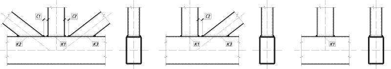
The Truss Panel Points mode enables to design and check the joints of the truss with the bars made of double angles or rectangular (square) hollow sections. The mode implements a wide range of the types of joints:
|
||
(a) |
(b) |
(c) |
|
||
(d) (g) |
||
|
||
(f) |
(g) |
(h) |
|
||
(i) |
(k) |
(l) |
Figure 1. Regular joints in trusses with elements made of double angles |
||
|
||
(a) |
(b) |
(c) |
|
||
(d) |
(e) |
(f) |
|
||
(g) (h) |
||
|
||
(i) |
(k) |
(l) |
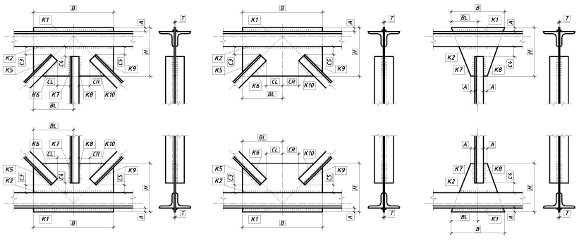
Figure 2. Regular joints in trusses with elements made of rectangular (square) hollow sections. |
||
а |
б |
|
|
Figure 3. Support joints in trusses with elements made of rectangular (square) hollow sections. |
|
|
|
(a) |
(b) |
|
|
(c) |
(d) |
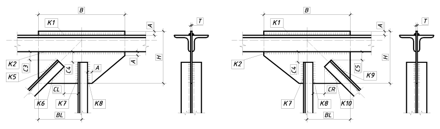
Figure 4. Joints where the chord changes its cross-section in trusses with elements made of double angles. |
|
|
|
(a) |
(b) |
|
|
(c) |
(d) |
|
|
(e) |
(f) |
|
|
(g) |
(h) |
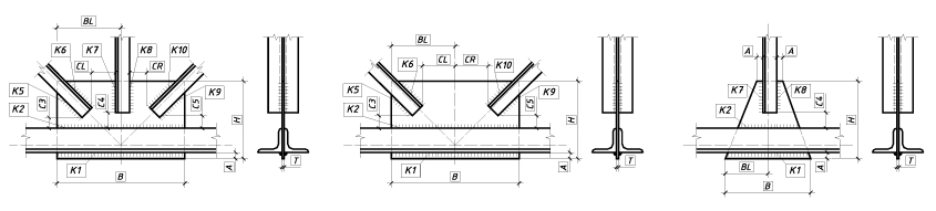
Figure 5. Erection joints in trusses with elements made of double angles. |
|
|
||
(a) |
(b) |
(c) |
|
||
(d) (e) |
||
Figure 6. Support joints in trusses with elements made of double angles. |
||
The mode performs the following checks in compliance with SNiP, SP, and DBN:
The Truss Panel Points dialog box contains seven tabs: Type of Joint, Materials, Forces, Joint Members, Structure, Drawing, and Interaction Curves.
The Type of Joint tab contains buttons which are used to select the type of a truss joint (Regular Joint, Section Change, Erection Joint, or Support Joint) and to specify its configuration. You can define the type of cross-section for the bar members of the truss by using the respective buttons in the Structure group.
This tab also contains the Stamp button used to fill in the stamp of the drawing, which will be generated automatically once the structural design of the truss joint is completed. The Stamp dialog box is described in Rigid Column Bases.
The Materials tab enables to
specify the materials used in the truss joint. The General
properties group displays the steel grade of the bearing and structural
members of the joint (brace members, truss chord, gusset plates, plates,
bearing stiffeners etc.). A steel grade for these members can be selected
in the Steel dialog box, which is invoked by clicking
the button  .
.
The Properties of joint group
contains drop-down lists which are used to select the type and method
of welding, and specify the position of the weld. The Truss
Panel Points mode implements the following methods of welding in
compliance with Table 34* of SNiP II-23-81* (Table 36 of SP 53-102-2004,
Table 38 of SP 16.13330, Table 1.12.2 of DBN B.2.6-163:2010,
or Table 16.2 of DBN B.2.6-198:2014): manual welding, semiautomatic
welding with solid wire less than 1.4 mm in diameter, automatic and
semiautomatic welding with the electrode wire 1.4 to 2.0 mm in diameter,
automatic welding with the electrode wire 3 to 5 mm in diameter,
and semiautomatic welding with flux-cored wire. The position of weld can
be underhand, flat, horizontal, vertical or overhead. The Properties
of welding materials group displays values of the design resistance
of the fillet welds for conventional shear of the weld metal, Rwf,
and of the characteristic resistance of the weld metal, Rwun.
These values can be specified in the Materials
for Welding dialog box, which is invoked by clicking the button  .
.
The Forces tab is used to specify axial forces Ni acting in the bar members of the truss joint. Clicking the Add button adds a new row to the table of internal forces, where you have to enter the values of internal forces for the current design combination of loads. There can be any number of design combinations of loads. The default units of measurement for axial forces are tonnes. The drawing next to the table of internal forces defines the positive directions of internal forces in the sections of the truss members.
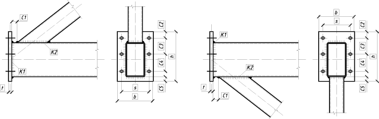
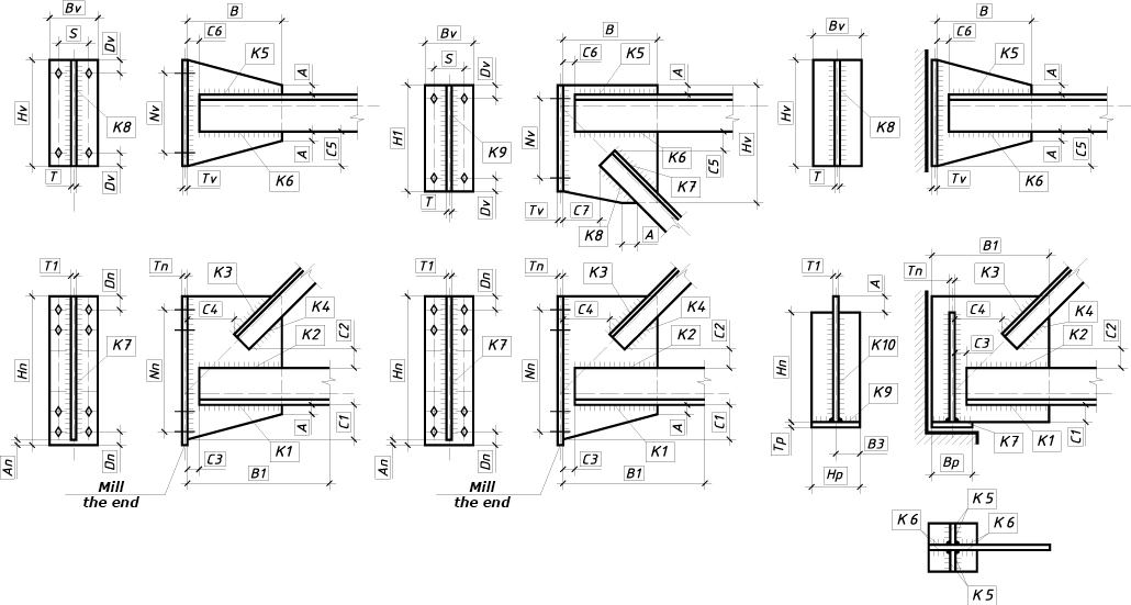
The Joint Members tab is used to specify the dimensions (width and height) of panels adjacent to the considered truss panel point (parameters a, b, c, and d). The default units of measurement for the dimensions of truss panels are meters. The Section group is used to specify the cross-sections of members connected in the considered joint and their orientation with respect to the truss plane.
The Type of section buttons enable you to select:
|
a section of double equal angles or of double unequal angles with the longer leg perpendicular to the truss plane; |
|
a section of double equal angles or of double unequal angles with the longer leg parallel to the truss plane; |
|
a section of equal angles arranged as a cross, which is used for the verticals of an erection joint; |
|
a rectangular hollow section with the longer side parallel to the truss plane; |
|
a rectangular hollow section with the longer side perpendicular to the truss plane. |
It should be noted that the set of Type of section buttons depends on the design of the joint specified in the Structure group of the Type of Joint tab.
Each member of the truss joint is assigned a number (e.g.,  ).
To assign profiles to the truss members, you have to select the respective
radio button of the member and select a profile from the list of assortments
of rolled profiles. The specified cross-sections of the members of the
truss joint can be checked in the Preview
window, which can be invoked by clicking the Preview
button (
).
To assign profiles to the truss members, you have to select the respective
radio button of the member and select a profile from the list of assortments
of rolled profiles. The specified cross-sections of the members of the
truss joint can be checked in the Preview
window, which can be invoked by clicking the Preview
button ( ).
).
You have to specify the position of the gusset plate by clicking the respective buttons in the Position of the gusset plate group. The thickness of the gusset plate can be selected from the respective drop-down list, which provides a set of thickness values according to the assortment of sheet and plate steel.
The Structure tab provides a draft of the design for the truss joint.
To perform a check of the load-bearing capacity of the specified structural design of the truss joint, you have to specify all design parameters of the joint. The parameters include the sizes and thickness of structural members of the joint, leg lengths of welds, sizes which determine the mutual arrangement of members, diameters of bolts, the number of bolts, the number of bolt rows, etc. The parameters of the joint are entered in the table on the left. Leg lengths of the fillet welds are entered in the table at the bottom of the dialog. The default units of linear measurement are millimeters.
Clicking the Design button drops down a menu. If the first item, All parameters are not specified, is selected, the automatic selection of all parameters of the joint design is performed and it is assumed that the parameters of the joint design are not specified (are equal to zero), and their previously specified values are ignored. If the Some parameters are specified menu item is selected, the program will automatically determine the values of the undefined (are equal to zero) parameters from the conditions of the adequate resistance and structural constraints defined by the standards with fixed values of the specified parameters.
Moreover, this mode calculates the value of maximum factor Kmax (a utilization factor of restrictions), indicates the type of the check in which this maximum took place, and generates the drawing of the joint design of the MS (metal structures) stage.
Clicking the Calculate button will perform the check of the load-bearing capacity of the specified joint members and of the connections between them according to the selected building code. The result will include the value of the maximum factor, Kmax (a utilization factor of restrictions) and the type of the check in which this maximum took place. A complete list of checks and values of the respective utilization factors of restrictions can be obtained by clicking the Factors button. The list of the load-bearing capacity checks of the members and connections of the truss joints performed by the application is given in the table below.
Check |
Type of joint |
SNiP II-23-81* |
SP 53-102-2004 |
SP 16.13330 |
DBN B.2.6-163:2010 |
DBN B.2.6-198:2014 |
ShNK 2.03.05-13 |
СН КР 53-01:2024 |
|---|---|---|---|---|---|---|---|---|
Regular joints in trusses with elements made of double angles: |
Fig. 1 |
|||||||
Resistance of the welded connection between the truss chord and the gusset plate |
a, b, c, d, e, f, g, h, i, j, k |
Sec. 11.2, (120), (121) |
Sec. 15.1.16, (155), (156) |
Sec. 14.1.16, (176), (177) |
Sec. 1.12.1.16, (1.12.2), (1.12.3) |
Sec. 16.1.16, (16.2), (16.3) |
Sec. 13.2, (129), (130) |
Sec. 13.2, (129), (130) |
Resistance of the welded connection between the vertical and the gusset plate |
a, c, d, e, f, h, i, j, k |
Sec. 11.2, (120), (121) |
Sec. 15.1.16, (155), (156) |
Sec. 14.1.16, (176), (177) |
Sec. 1.12.1.16, (1.12.2), (1.12.3) |
Sec. 16.1.16, (16.2), (16.3) |
Sec. 13.2, (129), (130) |
Sec. 13.2, (129), (130) |
Resistance of the welded connection between the left diagonal and the gusset plate |
a, b, d, f, g, i, k |
Sec. 11.2, (120), (121) |
Sec. 15.1.16, (155), (156) |
Sec. 14.1.16, (176), (177) |
Sec. 1.12.1.16, (1.12.2), (1.12.3) |
Sec. 16.1.16, (16.2), (16.3) |
Sec. 13.2, (129), (130) |
Sec. 13.2, (129), (130) |
Resistance of the welded connection between the right diagonal and the gusset plate |
a, b, e, f, g, j |
Sec. 11.2, (120), (121) |
Sec. 15.1.16, (155), (156) |
Sec. 14.1.16, (176), (177) |
Sec. 1.12.1.16, (1.12.2), (1.12.3) |
Sec. 16.1.16, (16.2), (16.3) |
Sec. 13.2, (129), (130) |
Sec. 13.2, (129), (130) |
Regular joints in trusses with elements made of rectangular (square) hollow sections: |
Fig. 2 |
|||||||
Punching shear resistance of the chord web |
a, b, c, d, e, f, g, h, i, j, k |
Sec. 15.10, 15.11, (92), (94) [3] |
Sec. R.2.2, (R.1), Sec. R.2.3, (R.2) |
Sec. L.2.2, (L.1), Sec. L.2.3, (L.2) Sec. 14.3.2 (86), (87) [139] |
Sec. U.1.2, (U.1), Sec. U.1.3, (U.2) |
Sec. М.6, М.7, (М.7), (М.8) |
Sec. L.6, L.7, (L.7), (L.8) Annex L |
|
Resistance of the chord web in the joint plane at the connection with the vertical |
a, b, c, d, e, f, h, j, k |
Sec. 15.12, (95) [3] |
Sec. R.2.4, (R.3) |
Sec. L.2.4, (L.3) Sec. 14.3.2 (88) [139] |
Sec. U.1.4, (U.3) |
Sec. М.8 (М.9) |
п. L.8, (L.9) Annex L |
|
Resistance of the chord web in the joint plane at the connection with the left diagonal |
a, d, g, h, i, , j, k |
Sec. 15.12, (95) [3] |
Sec. R.2.4, (R.3) |
Sec. L.2.4 (L.3) Sec. 14.3.2 (88) [139] |
Sec. U.1.4, (U.3) |
Sec. М.8 (М.9) |
Sec. L.8, (L.9) Annex L |
|
Resistance of the chord web in the joint plane at the connection with the left diagonal |
a, b, d, e, g, i |
Sec. 15.12, (95) [3] |
Sec. R.2.4, (R.3) |
Sec. L.2.4 (L.3) Sec. 14.3.2 (88) [139] |
Sec. U.1.4, (U.3) |
Sec. М.8 (М.9) |
Sec. L.8, (L.9) Annex L |
|
Resistance of the vertical at the connection with the chord |
a, b, c, d, e, f, h, , j, k |
Sec. 15.13, (96), (97) [3] |
Sec. R.2.5, (R.4), (R.5) |
Sec. L.2.5 (L.4), (L.5) Sec. 14.3.2 (89), (90) [139] |
Sec. U.1.5, (U.4), (U.5) |
Sec. М.9, (М.10), (М.11) |
Sec L.9, (L.10), (L.11) Annex L |
|
Resistance of the left diagonal at the connection with the chord |
a, d, g, h, i, , j, k |
Sec. 15.13, (96), (97) [3] |
Sec. R.2.5, (R.4), (R.5) |
Sec. L.2.5 (L.4), (L.5) Sec. 14.3.2 (89), (90) [139] |
Sec. U.1.5, (U.4), (U.5) |
Sec. М.9, (М.10), (М.11) |
Sec. L.9, (L.10), (L.11) Annex L |
|
Resistance of the right diagonal at the connection with the chord |
a, b, d, e, g, i |
Sec. 15.13, (96), (97) [3] |
Sec. R.2.5, (R.4), (R.5) |
Sec. L.2.5 (L.4), (L.5) Sec. 14.3.2 (89), (90) [139] |
Sec. U.1.5, (U.4), (U.5) |
Sec. М.9, (М.10), (М.11) |
Sec. L.9, (L.10), (L.11) Annex L |
|
Resistance of the welded connection between the vertical and the chord |
a, b, c, d, e, f, h, , j, k |
Sec. 15.14, (98), (99) [3] |
Sec. R.2.6, (R.6), (R.7) |
Sec. L.2.6 (L.6), (L.7) Sec. 14.3.2 (91), (92) [139] |
Sec. U.1.6, (U.6), (U.7) |
Sec. М.10, (М.12), (М.13) |
Sec. L.10, (L.12), (L.13) Annex L |
|
Resistance of the welded connection between the left diagonal and the chord |
a, d, g, h, i, , j, k |
Sec. 15.14, (98), (99) [3] |
Sec. R.2.6, (R.6), (R.7) |
Sec. L.2.6 (L.6), (L.7) Sec. 14.3.2 (91), (92) [139] |
Sec. U.1.6, (U.6), (U.7) |
Sec. М.10, (М.12), (М.13) |
Sec. L.10, (L.12), (L.13) Annex L |
|
Resistance of the welded connection between the right diagonal and the chord |
a, b, d, e, g, i |
Sec. 15.14, (98), (99) [3] |
Sec. R.2.6, (R.6), (R.7) |
Sec. L.2.6 (L.6), (L.7) Sec. 14.3.2 (91), (92) [139] |
Sec. U.1.6, (U.6), (U.7) |
Sec. М.10, (М.12), (М.13) |
Sec. L.10, (L.12), (L.13) Annex L |
|
Support joints in trusses with elements made of rectangular (square) hollow sections: |
Fig. 3 |
|||||||
Local bearing resistance of the bearing stiffener |
a, b |
Sec. 5.38 |
Sec. 16.12 |
Sec. 15.12 |
Sec. 1.8 |
Sec. 12 |
Sec. 7.38 |
Sec. 7.38 |
Stability of the bearing stiffener |
a, b |
Sec. 7.12 |
Sec. 9.5.13 |
Sec. 8.5.17, Sec. 7.1.3, (7) |
Sec. 1.5.5.13, Sec. 1.4.1.3, (1.4.3) |
Sec. 9.5.13, Sec. 8.1.3, (8.3) |
Sec. 9.13 |
Sec. 9.13 |
Punching shear resistance of the chord web |
a, b |
Sec. 15.10, 15.11, (92), (94) [3] |
Sec. R.2.2, (R.1), Sec. R.2.3, (R.2) |
Sec. L.2.2, (L.1), Sec. L.2.3, (L.2) Sec. 14.3.2 (86), (87) [139] |
Sec. М.6, М.7, (М.7), (М.8) |
Sec. L.6, L.7, (L.7), (L.8) Annex L |
||
Resistance of the chord web in the joint plane at the connection with the support diagonal |
a, b |
Sec. 15.12, (95) [3] |
Sec. R.2.4, (R.3) |
Sec. L.2.4, (L.3) Sec. 14.3.2 (88) [139] |
Sec. М.8 (М.9) |
Sec. L.8, (L.9) Annex L |
||
Resistance of the support diagonal at the connection with the chord |
a, b |
Sec. 15.13, (96), (97) [3] |
Sec. R.2.5, (R.4), (R.5) |
Sec. L.2.5, (L.4), (L.5) Sec. 14.3.2 (89), (90) [139] |
Sec. М.9, (М.10), (М.11) |
Sec. L.9, (L.10), (L.11) Annex L |
||
Resistance of the welded connection between the chord and the bearing stiffener |
a, b |
Sec. 11.2, (120), (121) [3] |
Sec. 15.1.16, (155), (156) |
Sec. 14.1.16, (176), (177) |
Sec. 1.12.1.16, (1.12.2), (1.12.3) |
Sec. 16.1.16, (16.2), (16.3) |
Sec. 13.2, (129), (130) |
Sec. 13.2, (129), (130) |
Resistance of the welded connection between the support diagonal and the chord |
a, b |
Sec. 15.14, (98), (99) [3] |
Sec. R.2.6, (R.6), (R.7) |
Sec. L.2.6, (L.6), (L.7) Sec. 14.3.2 (91), (92) |
Sec. М.10, (М.12), (М.13) |
Sec. L.10, (L.12), (L.13) Annex L |
||
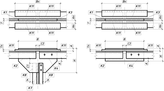
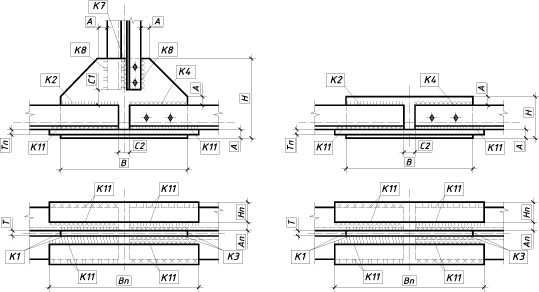
Joints where the chord changes its cross-section in trusses with elements made of double angles: |
Fig. 4 |
|||||||
Resistance of the welded connection between the truss chord and the gusset plate |
a, b, c, d |
Sec. 11.2, (120), (121) |
Sec. 15.1.16, (155), (156) |
Sec. 14.1.16, (176), (177) |
Sec. 1.12.1.16, (1.12.2), (1.12.3) |
Sec. 16.1.16, (16.2), (16.3) |
Sec. 13.2, (129), (130) |
Sec. 13.2, (129), (130) |
Resistance of the welded connection between the vertical and the gusset plate |
a, c |
Sec. 11.2, (120), (121) |
Sec. 15.1.16, (155), (156) |
Sec. 14.1.16, (176), (177) |
Sec. 1.12.1.16, (1.12.2), (1.12.3) |
Sec. 16.1.16, (16.2), (16.3) |
Sec. 13.2, (129), (130) |
Sec. 13.2, (129), (130) |
Resistance of the welded connection between the left diagonal and the gusset plate |
a, b, c, d |
Sec. 11.2, (120), (121) |
Sec. 15.1.16, (155), (156) |
Sec. 14.1.16, (176), (177) |
Sec. 1.12.1.16, (1.12.2), (1.12.3) |
Sec. 16.1.16, (16.2), (16.3) |
Sec. 13.2, (129), (130) |
Sec. 13.2, (129), (130) |
Resistance of the welded connection between the right diagonal and the gusset plate |
a, b, c, d |
Sec. 11.2, (120), (121) |
Sec. 15.1.16, (155), (156) |
Sec. 14.1.16, (176), (177) |
Sec. 1.12.1.16, (1.12.2), (1.12.3) |
Sec. 16.1.16, (16.2), (16.3) |
Sec. 13.2, (129), (130) |
Sec. 13.2, (129), (130) |
Resistance of the plate |
a, b, c, d |
Sec. 5.1, (5) |
Sec. 8.1.1, (5) |
Sec. 7.1.1, (5) |
Sec. 1.4.1.1, (1.4.1) |
Sec. 8.1.1, (8.1) |
Sec. 7.1, (1) |
Sec. 7.1, (1) |
Resistance of the welded connection between a plate and a chord flange with a greater cross-section |
a, b, c, d |
Sec. 11.2, (120), (121) |
Sec. 15.1.16, (155), (156) |
Sec. 14.1.16, (176), (177) |
Sec. 1.12.1.16, (1.12.2), (1.12.3) |
Sec. 16.1.16, (16.2), (16.3) |
Sec. 13.2, (129), (130) |
Sec. 13.2, (129), (130) |
Resistance of the welded connection between a plate and a chord flange with a smaller cross-section |
a, b, c, d |
Sec. 11.2, (120), (121) |
Sec. 15.1.16, (155), (156) |
Sec. 14.1.16, (176), (177) |
Sec. 1.12.1.16, (1.12.2), (1.12.3) |
Sec. 16.1.16, (16.2), (16.3) |
Sec. 13.2, (129), (130) |
Sec. 13.2, (129), (130) |
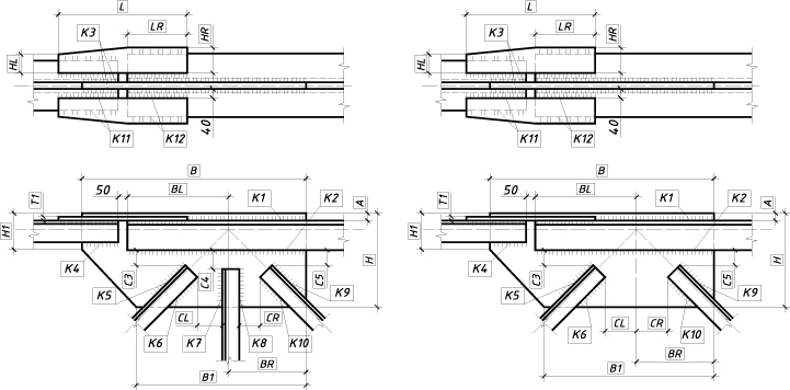
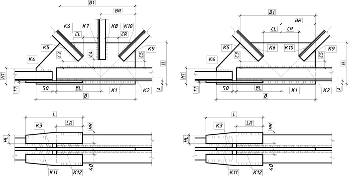
Erection joints in trusses with elements made of double angles: |
Fig. 5 |
|||||||
Resistance of the welded connection between the chord of the left truss panel and the gusset plate |
a, b, c, d, e, f, g, h |
Sec. 11.2, (120), (121) |
Sec. 15.1.16, (155), (156) |
Sec. 14.1.16, (176), (177) |
Sec. 1.12.1.16, (1.12.2), (1.12.3) |
Sec. 16.1.16, (16.2), (16.3) |
Sec. 13.2, (129), (130) |
Sec. 13.2, (129), (130) |
Resistance of the welded connection between the chord of the right truss panel and the gusset plate |
a, b, c, d, e, f, g, h |
Sec. 11.2, (120), (121) |
Sec. 15.1.16, (155), (156) |
Sec. 14.1.16, (176), (177) |
Sec. 1.12.1.16, (1.12.2), (1.12.3) |
Sec. 16.1.16, (16.2), (16.3) |
Sec. 13.2, (129), (130) |
Sec. 13.2, (129), (130) |
Resistance of the welded connection between the vertical of the left truss panel and the gusset plate |
a, c, e, g |
Sec. 11.2, (120), (121) |
Sec. 15.1.16, (155), (156) |
Sec. 14.1.16, (176), (177) |
Sec. 1.12.1.16, (1.12.2), (1.12.3) |
Sec. 16.1.16, (16.2), (16.3) |
Sec. 13.2, (129), (130) |
Sec. 13.2, (129), (130) |
Resistance of the welded connection between the vertical of the right truss panel and the gusset plate |
a, c, e, g |
Sec. 11.2, (120), (121) |
Sec. 15.1.16, (155), (156) |
Sec. 14.1.16, (176), (177) |
Sec.1.12.1.16, (1.12.2), (1.12.3) |
Sec. 16.1.16, (16.2), (16.3) |
Sec. 13.2, (129), (130) |
Sec. 13.2, (129), (130) |
Resistance of the welded connection between the left diagonal and the gusset plate |
a, b, e, f |
Sec. 11.2, (120), (121) |
Sec. 15.1.16, (155), (156) |
Sec. 14.1.16, (176), (177) |
Sec. 1.12.1.16, (1.12.2), (1.12.3) |
Sec. 16.1.16, (16.2), (16.3) |
Sec. 13.2, (129), (130) |
Sec. 13.2, (129), (130) |
Resistance of the welded connection between the right diagonal and the gusset plate |
a, b, e, f |
Sec. 11.2, (120), (121) |
Sec. 15.1.16, (155), (156) |
Sec. 14.1.16, (176), (177) |
Sec. 1.12.1.16, (1.12.2), (1.12.3) |
Sec. 16.1.16, (16.2), (16.3) |
Sec. 13.2, (129), (130) |
Sec. 13.2, (129), (130) |
Resistance of the plate |
a, b, c, d, e, f, g, h |
Sec. 5.1, (5) |
Sec. 8.1.1, (5) |
Sec. 7.1.1, (5) |
Sec.1.4.1.1, (1.4.1) |
Sec. 8.1.1, (8.1) |
Sec. 7.1, (1) |
Sec. 7.1, (1) |
Resistance of the welded connection between the plate and the chord flange of the left truss panel |
a, b, c, d, e, f, g, h |
Sec. 11.2, (120), (121) |
Sec. 15.1.16, (155), (156) |
Sec. 14.1.16, (176), (177) |
Sec. 1.12.1.16, (1.12.2), (1.12.3) |
Sec. 16.1.16, (16.2), (16.3) |
Sec. 13.2, (129), (130) |
Sec. 13.2, (129), (130) |
Resistance of the welded connection between the plate and the chord flange of the right truss panel |
a, b, c, d, e, f, g, h |
Sec. 11.2, (120), (121) |
Sec. 15.1.16, (155), (156) |
Sec. 14.1.16, (176), (177) |
Sec. 1.12.1.16, (1.12.2), (1.12.3) |
Sec. 16.1.16, (16.2), (16.3) |
Sec. 13.2, (129), (130) |
Sec. 13.2, (129), (130) |
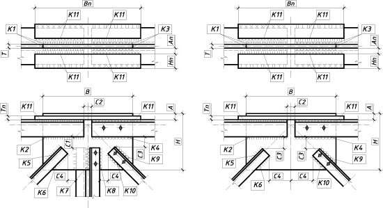
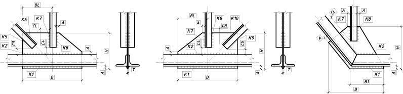
Support joints in trusses with elements made of double angles: |
Fig. 6 |
|||||||
Shear and bearing strength of bolts |
e |
Sec. 11.7*, (127), (128), Sec. 11.8, (130) |
Sec. 15.2.9, (165), (166), Sec. 15.2.10, (168) |
Sec. 14.2.9, (186), (187), Sec. 14.2.10, (189) |
Sec. 1.12.2.9, (1.12.12), (1.12.13), Sec. 1.12.2.10, (1.12.15) |
Sec. 16.2.9, (16.12), (16.13), Sec. 16.2.10, (16.15) |
Sec. 13.7, (136), (137), Sec. 13.8, (139) |
Sec. 13.7, (136), (137), Sec. 13.8, (139) |
Tensile strength of bolts |
a, b, e |
Sec. 11.7*, (129), Sec. 11.8, (130) |
Sec. 15.2.9, (165), (166), Sec. 15.2.10, (168) |
Sec. 14.2.9, (188), Sec. 14.2.10, (189) |
Sec. 1.12.2.9, (1.12.12), (1.12.13), Sec. 1.12.2.10, (1.12.15) |
Sec. 16.2.9, (16.14), Sec. 16.2.10, (16.15) |
Sec. 13.7, (138), Sec. 13.8, (139) |
Sec. 13.7, (138), Sec. 13.8, (139) |
Bending resistance of the end-plate |
a, b |
Sec. 5.12, (28) |
Sec. 9.2.1, (35) |
Sec. 8.2.1, (41) |
Sec. 1.5.2.1, (1.5.1) |
Sec. 9.2.1, (9.1) |
Sec. 7.12, (24) |
Sec. 7.12, (24) |
Local bearing resistance of the bearing stiffener |
e |
Sec. 5.38 |
Sec. 16.12 |
Sec. 15.12 |
Sec. 1.8 |
Sec. 12 |
Sec. 7.38 |
Sec. 7.38 |
Stability of the bearing stiffener |
e |
Sec. 7.12 |
Sec. 9.5.13 |
Sec. 8.5.17, Sec. 7.1.3, (7) |
Sec. 1.5.5.13, Sec. 1.4.1.3, (1.4.3) |
Sec. 9.5.13, Sec. 8.1.3, (8.3) |
Sec. 9.13 |
Sec. 9.13 |
Local stability of the overhangs of the bearing stiffener flanges |
e |
Sec. 7.23*, Table 29* |
Sec. 8.3.7, (31) |
Sec. 7.3.8, (37) |
Sec. 1.4.3.7, (1.4.27) |
Sec. 8.3.7, (8.27) |
Sec. 9.23 |
Sec. 9.23 Table 22 |
Resistance of the welded connection between the chord and the support gusset |
a, b, c, d, e, f |
Sec. 11.2, (120), (121) |
Sec. 15.1.16, (155), (156) |
Sec. 14.1.16, (176), (177) |
Sec. 1.12.1.16, (1.12.2), (1.12.3) |
Sec. 16.1.16, (16.2), (16.3) |
Sec. 13.2, (129), (130) |
Sec. 13.2, (129), (130) |
Resistance of the welded connection between the support diagonal and the support gusset |
b, c, d, e, f |
Sec. 11.2, (120), (121) |
Sec. 15.1.16, (155), (156) |
Sec. 14.1.16, (176), (177) |
Sec. 1.12.1.16, (1.12.2), (1.12.3) |
Sec. 16.1.16, (16.2), (16.3) |
Sec. 13.2, (129), (130) |
Sec. 13.2, (129), (130) |
Resistance of the welded connection between the bearing stiffener and the support gusset |
d, e, f |
Sec. 11.2, (120), (121), Sec. 11.3*, (122), (123), Sec. 11.5, (126) |
Sec. 15.1.16, (155), (156), Sec. 15.1.17, (157), (158), Sec. 15.1.19, (161), (162) |
Sec. 14.1.16, (176), (177), Sec. 14.1.17, (178), (179), Sec. 14.1.19, (182), (183) |
Sec. 1.12.1.16, (1.12.2), (1.12.3), Sec. 1.12.1.17, (1.12.4), (1.12.5), Sec. 1.12.1.19, (1.12.8), (1.12.9) |
Sec. 16.1.16, (16.2), (16.3), Sec. 16.1.17, (16.4), (16.5), Sec. 16.1.19, (16.8), (16.9) |
Sec. 13.2, (129), (130), Sec. 13.3, (131), (132), Sec. 13.5, (135) |
Sec. 13.2, (129), (130) Sec. 13.3, (131), (132), Sec. 13.5, (135) |
Resistance of the welded connection between the end-plate and the support gusset |
a, b, c |
Sec. 11.2, (120), (121), Sec. 11.3*, (122), (123), Sec. 11.5, (126) |
Sec. 15.1.16, (155), (156),Sec. 15.1.17, (157), (158), Sec. 15.1.19, (161), (162) |
Sec. 14.1.16, (176), (177), Sec. 14.1.17, (178), (179), Sec. 14.1.19, (182), (183) |
Sec. 1.12.1.16, (1.12.2), (1.12.3), Sec. 1.12.1.17, (1.12.4), (1.12.5), Sec. 1.12.1.19, (1.12.8), (1.12.9) |
Sec. 16.1.16, (16.2), (16.3), Sec. 16.1.17, (16.4), (16.5), Sec. 16.1.19, (16.8), (16.9) |
Sec. 13.2, (129), (130), Sec. 13.3, (131), (132), Sec. 13.5, (135) |
Sec. 13.2, (129), (130) Sec. 13.3, (131), (132), Sec. 13.5, (135) |
Resistance of the base plate |
d, f |
Sec. 5.12, (28) |
Sec. 9.6.2 (86-88) |
Sec. 8.6.2 (101-103) |
Sec. 1.7.2, (1.7.1), Annex N, (N.1), (N2), Table N.2 |
Sec. 11.2, (11.1), Annex. M, Sec. M.2, (M.1), (M.2) |
Sec. 7.12, (24) |
Sec. 7.12, (24) |
Notes: see the table in the Rigid Column Bases section. |
||||||||
Once you switch to the Drawing tab, the application performs a check of the truss joint similarly to the Calculate mode. If the results of the check of the parameters of the joint members do not contradict the structural and standard requirements, a drawing of the joint design of the MS stage will be generated.