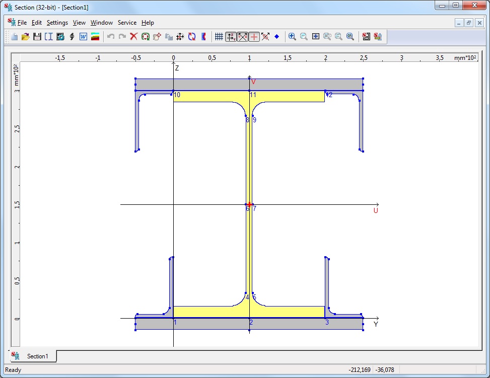
Section Builder enables you to create arbitrary compound sections from rolled steel profiles and plates, and calculate their geometric properties required for structural analysis.
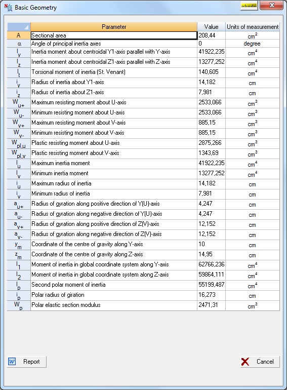
The following values are determined for the designed section:
- cross-sectional area А;
- values of the moments of inertia Iy and Iz around centroidal axes parallel to the coordinate axes of the right-handed Cartesian coordinate system Y and Z;
- radii of gyration iy and iz about the same axes;
- torsional moment of inertia It;
- coordinates of the center of mass;
- value of the angle of the principal axes of inertia (angle a between U and Y axes);
- maximum Iu and minimum Iv moments of inertia;
- maximum iu and minimum iv radii of gyration;
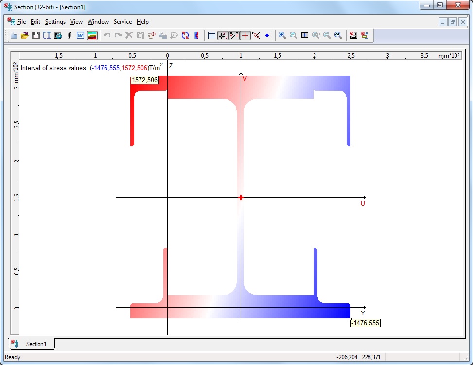
- maximum Wu+ and minimum Wu- section moduli about the U-axis;
- maximum Wv+ and minimum Wv- section moduli about the V-axis;
- core size from U-axis along the positive аu+ and negative аu- directions of V-axis;
- core distance along the positive Wv+ and negative Wv- directions of U-axis.
The calculations are performed according to the rules of strength of materials, the torsional moment of inertia is approximately determined as the sum of the torsional moments of inertia of profiles comprising the section.
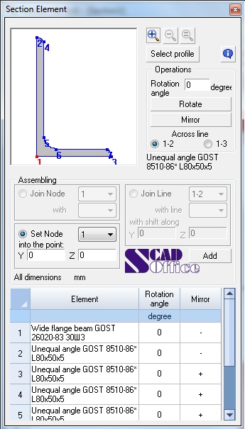
Assembling
Section Builder provides the following methods of assembling:
- joining an element by one of its nodes to a node of a section element;
- joining an element by one of its nodes to a section point defined by Y and Z coordinates;
- joining an element by merging lines that are going through two nodes of the new element and the selected element of the section.
When using the first two methods, the element is added to the section with a specified orientation. When joining by a line, the orientation of an element in the section is defined by orientation of the lines used to join the elements.
Report
A report containing properties of the selected section can be created. The report is the RTF (Rich Text Format) file. After the file is created, an application associated with the RTF is automatically invoked (e.g. MS Word or WordPad).
Exporting results
The results of the calculation of the geometric properties can be exported to SCAD and to Kristall.
Information on the cross-section components
You can also obtain information about rolled profiles which comprise the section.
Interface
Section Builder functions under Windows operating environment. All the windows, dialog boxes and controls are fully consistent with this environment.
Help (Reference Information)
The application is provided with a detailed help which includes descriptions of the user interface and conventions of using the application.