The Beam Splices mode enables to design and check the load-bearing capacity of erection joints between I- beams with high strength bolts or ordinary bolts using plates or end-plates. This mode comprises a wide range of designs for erection joints between beams:
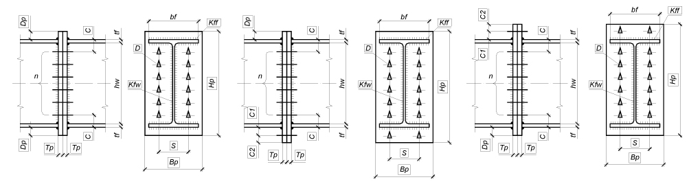
Figure 1. Design of a beam splice with plates
(а) |
(b) |
(c) |
|
||
(d) |
(e) |
|
|
(f) |
(g) |
|
|
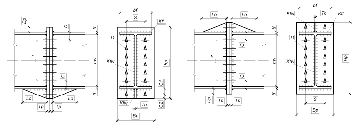
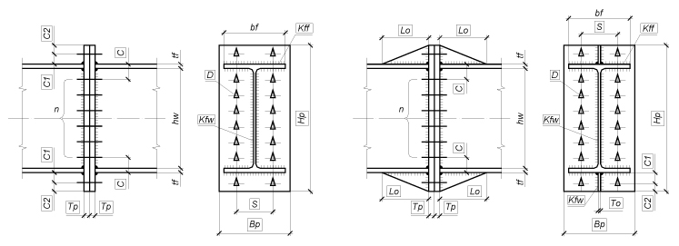
Figure 2. Types of designs for end-plate beam splices with the regular placement of bolts along the beam webs
|
(a) (b) (c) |
|
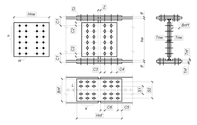
Figure 3.
Examples of types of end-plate beam splices with the irregular
placement of high strength bolts: |
The erection beam splice with plates has an advantage over the end-plate beam splices in that it does not require the members to be manufactured with a high accuracy. However, this kind of joint usually requires a much greater number of bolts in comparison to end-plate joints, therefore it takes more effort to mount the structures. Moreover, the joint with plates entails the weakening of the cross-sections of connected members by holes, which may in some cases require using more steel for the main structural members.
It should be noted that the computer-calculation of beam splices with plates assumes that the cross-sectional dimensions of the plates covering the beam splice are taken as close as possible to the cross-sectional dimensions of the beam. It refers to both the thickness of the plates, and to their linear dimensions (in particular, to the height of the plate on the beam webs and the width of the plates on the beam flanges). In the case when the height of the plate on the beam webs is assumed to be less than the effective height of the beam web, the stress concentrations should be calculated and taken into account in the check, which is not implemented in the program due to the absence of any standard methods for performing such a calculation.
End-plate joints are usually designed in such a way so that the height of the end-plate corresponds to that of the beam (Fig. 2, a, Fig. 3, a). If the bending moment acting in the beam splice can hardly be resisted by bolts placed between the beam flanges, it becomes necessary to use the designs that involve external bolt rows. The latter expand the end-plate dimension downward (Fig. 2, b, d, Fig. 3, b) or upward (Fig. 2, c, e, Fig. 3, a), depending on the prevailing sign of the bending moment. If there are significant alternating-sign bending moments, you should use end-plate joints with external bolts on both sides of the beam (Fig. 2, f, g).
This mode performs the following checks in compliance with SNiP, SP, or DBN:
The Beam Splices dialog box contains the following tabs: Materials, Forces, Structure, Welding, Drawing, and Interaction Curves.
First you have to specify the materials used in the beam splice. A steel
grade for the connected beams can be selected in the Steel
dialog box, which is invoked by clicking the button  in the Materials tab.
It should be noted that if the analysis and design are performed according to SNiP, SP, or DBN, the steel grade for structural members of the joint (plates or end-plate) is the same as that for the main (load-bearing) members (beams).
You can enter the service factor for beams in the respective text field,
or it can be selected in the Service Factor
dialog box after clicking the nearby button ( ).
).
The service factor of beams at their strength analysis for a section weakened by holes is calculated automatically in this mode.
The importance factor which will be further multiplied by the design values of all internal forces for all design combinations of loadings acting in the splice has to be specified in the Importance factor drop-down list in this tab.
Controls of the Profile group
are used to define the type and sizes of the cross-sections of spliced
beams. The Beam Splices mode provides
two types of beam cross-sections: rolled or welded I-section. The section
type is selected by clicking the respective button  or
or . The interface of the right part of the Materials
tab depends on this choice. If a rolled I-section is selected as the beam
cross-section type, you then have to select an assortment and the profile
number in this assortment from the tree-like list. When a welded I-section
is selected as the beam cross-section type, you have to specify the sizes
of the beam cross-section: the height, kw,
and the thickness, tw,
of the beam web; the width, bf,
and the thickness, tf,
of the beam flanges. The thickness of the flanges and of the web can be
either entered manually or selected from drop-down lists, which contain
the set of thickness values according to the assortment of sheet and plate
steel.
. The interface of the right part of the Materials
tab depends on this choice. If a rolled I-section is selected as the beam
cross-section type, you then have to select an assortment and the profile
number in this assortment from the tree-like list. When a welded I-section
is selected as the beam cross-section type, you have to specify the sizes
of the beam cross-section: the height, kw,
and the thickness, tw,
of the beam web; the width, bf,
and the thickness, tf,
of the beam flanges. The thickness of the flanges and of the web can be
either entered manually or selected from drop-down lists, which contain
the set of thickness values according to the assortment of sheet and plate
steel.
The beam cross-section can be checked in the Preview
window, which can be invoked by clicking the Preview
button ( ).
).
Clicking the Stamp button opens a dialog box which enables to fill in the stamp of the drawing, which will be generated automatically once the structural design of the beam splice is completed. The Stamp dialog box is described in Rigid Column Bases.
The Welding tab enables to specify
the parameters of the welded connections for the joint. The
Properties of joint contains drop-down lists which are used
to select the type and method of welding, and specify the position of
the weld. This mode implements the following methods of welding in compliance
with Table 34* of SNiP II-23-81* (Table 36 of SP 53-102-2004,
Table 38 of SP 16.13330, Table 1.12.2 of DBN B.2.6-163:2010,
or Table 16.2 of DBN B.2.6-198:2014): manual welding, semiautomatic
welding with solid wire less than 1.4 mm in diameter, automatic and
semiautomatic welding with the electrode wire 1.4 to 2.0 mm in diameter,
automatic welding with the electrode wire 3 to 5 mm in diameter,
and semiautomatic welding with flux-cored wire. The position of weld can
be underhand, flat, horizontal, vertical or overhead. The Properties
of welding materials group displays values of the design resistance
of the fillet welds for conventional shear of the weld metal, Rwf,
and of the characteristic resistance of the weld metal, Rwun.
These values can be specified in the Materials
for Welding dialog box, which is invoked by clicking the button  .
.
The Forces tab is used to specify the internal forces acting in the beam splice: the axial force, N, the bending moment, M, and its respective shear force, Q. Thus the general case of loading is implemented when the given splice can be used both in the beams of floors and roofs, and in the girders of transverse steel frames. Clicking the Add button adds a new row to the table of internal forces, where you have to enter the values of internal forces for the current design combination of loads. There can be any number of design combinations of loads. The default units of measurement for axial and shear forces are tonnes, and for bending moments – tonne×meter. The positive direction of internal forces is defined by the picture to the left from the table of internal forces.
It should be noted that if the values of the internal forces in the beam splice have been obtained from the analysis of the respective finite element model of the system accounting for the importance of the designed building or structure, the value equal to one has to be selected in the Importance factor drop-down list in the Materials tab.
The table can be also filled by importing the data from SCAD
which describe the design combinations of forces (DCF). A file with the
.rsu2 extension is created in
the Element Information mode of
the SCAD software and then can
be imported by clicking the button  .
It should be noted that when creating an .rsu2
file in SCAD, the table of design
combinations should include only those combinations that correspond to
the section of the bar element adjacent to the node.
.
It should be noted that when creating an .rsu2
file in SCAD, the table of design
combinations should include only those combinations that correspond to
the section of the bar element adjacent to the node.
The Structure tab contains buttons of the Type of joint group, which are used to select a design for the beam splice.
If the design is performed according to SNiP, SP, or DBN and bolts of normal and improved strength are used, you have to select the grade (diameter) of the bolts and their strength class from the drop-down lists of the Bolts group. If high strength bolts are used, you have to specify the grade (diameter) of the bolts, their steel grade, their clearance (the difference between the diameter of the bolt hole and of the bolt itself), a bolt tightening control method, and a method of cleaning the surfaces to be joined.
In the case when the user has to perform the analysis or design of end-plate beam splices with the irregular placement of bolts, he can use the Placement of bolts with respect to the beam group of interface elements which enables to specify the regular or irregular placement of bolts along the web, and to select the design of a splice with an additional bolt row along the beam flanges (usually in tension).
To perform a check of the load-bearing capacity of a known (specified) structural design of the beam splice, you have to specify all parameters of the joint: the sizes and thickness of structural members of the joint, diameters of bolts, sizes which determine the mutual arrangement of members, leg lengths of welds, the number of bolts, the number of bolt rows, etc. The parameters of the joint are entered in the table on the right in the Structure tab. The default units of linear measurement are millimeters.
Clicking the Design button drops down a menu. If the first item, All parameters are not specified, is selected, the automatic selection of all parameters of the joint design is performed and it is assumed that the parameters of the joint design are not specified (are equal to zero), and their previously specified values are ignored. If the Some parameters are specified menu item is selected, the program will automatically determine the values of the undefined (are equal to zero) parameters with fixed values of the specified parameters.
The automatic selection of the beam splice design is performed on the basis of the analysis of its sensitivity with respect to the variation of the controlled parameters of the joint taking into account the conditions of the adequate resistance and structural constraints defined by the standards (see General Information). The diameter of bolts and the number of bolt rows have been selected as the controlled parameters of the beam splice joint structures for an erection beam splice with plates, and the diameter of bolts, thickness of the end-plate and the number of bolt rows – for the erection end-plate beam splices.
Clicking the Calculate button will perform the check of the load-bearing capacity of the specified joint members and of the connections between them according to SNiP, SP, or DBN.
After clicking the Design or Calculate button the maximum utilization factor of restrictions (the most dangerous) will be displayed in the Kmax field located in the lower part of the dialog box, and the type of the standard check (strength, stability, local stability, etc.) in which this maximum took place will be indicated, and a drawing of the beam splice joint design of the MS stage will be generated.
A complete list of the performed checks and values of the respective utilization factors of restrictions can be obtained by clicking the Factors button.
A complete list of the performed checks can be obtained by clicking the Factors button. It will be displayed in the special Factors Diagram dialog box, where you can browse the values of all utilization factors of restrictions. The list of the load-bearing capacity checks of the members and connections of the joints of the beam splices performed by the application is given in table below.
Clicking the Report button generates a report document which contains the initial data and the results of analysis.
The dialog box also contains three buttons: 

 , which enable to perform the following operations:
— if the
forces are specified, clicking this button will draw the points the coordinates
of which in the area of the load-bearing capacity correspond to these
forces;
— drawing
a convex hull of the points specified above, i.e. an entire set of points
which may result from a linear combination of specified forces, including
their incomplete values;
— saving the
forces that can lead to Kmax=1
in a text file (this file can be imported into other programs for further
analysis).
Check |
Type of splice |
SNiP II-23-81* and the Guide [3] |
SP 53-102-2004 |
SP 16.13330 |
DBN B.2.6-163:2010 |
DBN B.2.6-198:2014 |
ShNK 2.03.05-13 |
SN KR 53-01:2024 |
|---|---|---|---|---|---|---|---|---|
Shear strength of bolts in the bolted connection of the beam web |
Fig. 1 |
Sec. 11.7*, (127), (130) |
Sec. 15.2.9, (165), (168) |
Sec. 14.2.9, (186), (189) |
Sec. 1.12.2.9, (1.12.12), (1.12.15) |
Sec. 16.2.9, (16.12), (16.15) |
Sec. 13.7, (136), (139) |
Sec. 13.7, (136), (139) |
Shear strength of bolts in the bolted connection of the beam flange |
Fig. 1 |
Sec. 11.7*, (127), (130) |
Sec. 15.2.9, (165), (168) |
Sec. 14.2.9, (186), (189) |
Sec. 1.12.2.9, (1.12.12), (1.12.15) |
Sec. 16.2.9, (16.12), (16.15) |
Sec. 13.7, (136), (139) |
Sec. 13.7, (136), (139) |
Bearing resistance of the beam web and plates |
Fig. 1 |
Sec. 11.7*, (128), (130) |
Sec. 15.2.9, (166), (168) |
Sec. 14.2.9, (187), (189) |
Sec. 1.12.2.9, (1.12.13), (1.12.15) |
Sec. 16.2.9, (16.13), (16.15) |
Sec. 13.7, (137), (139) |
Sec. 13.7, (137), (139) |
Bearing resistance of the beam flange and plates |
Fig. 1 |
Sec. 11.7*, (128), (130) |
Sec. 15.2.9, (166), (168) |
Sec. 14.2.9, (187), (189) |
Sec. 1.12.2.9, (1.12.13), (1.12.15) |
Sec. 16.2.9, (16.13), (16.15) |
Sec. 13.7, (137), (139) |
Sec. 13.7, (137), (139) |
Strength of bolts in the bolted connection of the beam web |
Fig. 1 |
Sec. 11.13*, (131), (132) |
Sec. 15.3.3, (170), (171) |
Sec. 14.3.3, (191), (192) |
Sec. 1.12.3.3, (1.12.17), (1.12.18) |
Sec. 16.3.3, (16.17), (16.18) |
Sec. 13.13, (140), (141) |
Sec. 13.13, (140), (141) |
Strength of bolts in the bolted connection of the beam flange |
Fig. 1 |
Sec. 11.13*, (131), (132) |
Sec. 15.3.3, (170), (171) |
Sec. 14.3.3, (191), (192) |
Sec. 1.12.3.3, (1.12.17), (1.12.18) |
Sec. 16.3.3, (16.17), (16.18) |
Sec. 13.13, (140), (141) |
Sec. 13.13, (140), (141) |
Strength of bolts located in the area of the top beam flange |
Fig. 2 |
Sec. 27.13 [3] |
Sec. 16.9.2 |
Sec. 12.3.12 (SP 294.1325800.2017) |
Sec. 1.13.12.2 |
Sec. 17.12.2 |
– |
Sec. 27.13 [3] |
Strength of bolts located in the area of the bottom beam flange |
Fig. 2 |
Sec. 27.13 [3] |
Sec. 16.9.2 |
Sec. 12.3.12 (SP 294.1325800.2017) |
Sec. 1.13.12.2 |
Sec. 17.12.2 |
– |
Sec. 27.13 [3] |
Strength of bolts located in the area of the beam web |
Fig. 2 |
Sec. 27.13 [3] |
Sec. 16.9.2 |
Sec. 12.3.12 (SP 294.1325800.2017) |
Sec. 1.13.12.2 |
Sec. 17.12.2 |
– |
Sec. 27.13 [3] |
Strength of the end-plate connection subjected to shear force |
Fig. 2 |
27.14 [3] |
Sec. 16.9.2 |
Sec.12.3.13 (SP 294.1325800.2017) |
Sec. 1.13.12.2 |
Sec. 17.12.2 |
– |
27.14 [3] |
Bending resistance of the end-plate |
Fig. 2 |
Sec. 27.13 [3] |
Sec. 16.9.2 |
Sec. 12.3.12 (SP 294.1325800.2017) |
Sec. 1.13.12.2 |
Sec. 17.12.2 |
– |
Sec. 27.13 [3] |
Resistance of the welded connection between the beam web and the end-plate |
Fig. 2 |
Sec. 11.2*, (120)-(123) |
Sec. 15.1.16, (155), (156), Sec. 15.1.17, (157), (158), Sec. 15.1.19, (161), (162) |
Sec. 14.1.16, (176), (177), Sec. 14.1.17, (178), (179), Sec. 14.1.19, (182), (183) |
Sec. 1.12.1.16, (1.12.2), (1.12.3), Sec. 1.12.1.17, (1.12.4), (1.12.5), Sec. 1.12.1.19, (1.12.8), (1.12.9) |
Sec. 16.1.16, (16.2), (16.3), Sec. 16.1.17, (16.4), (16.5), Sec. 16.1.19, (16.8), (16.9) |
Sec. 13.2, 13.3, (129)-(132) |
Sec. 13.2, (129)-(132) |
Resistance of the welded connection between the beam flange and the end-plate |
Fig. 2 |
Sec. 11.2*, (120)-(123) |
Sec. 15.1.16, (155), (156), Sec. 15.1.19, (161), (162) |
Sec. 14.1.16, (176), (177), Sec. 14.1.19, (182), (183) |
Sec. 1.12.1.16, (1.12.2), (1.12.3), Sec. 1.12.1.19, (1.12.8), (1.12.9) |
Sec. 16.1.16, (16.2), (16.3), Sec. 16.1.19, (16.8), (16.9) |
Sec. 13.2, 13.3, (129)-(132) |
Sec. 13.2, (129)-(132) |
Resistance of a plate on beam flanges |
Fig. 1 |
Sec. 5.1, (5) |
Sec. 8.1.1, (5) |
Sec. 7.1.1, (5) |
Sec. 1.4.1.1, (1.4.1) |
Sec. 8.1.1, (8.1) |
Sec. 7.1, (1) |
Sec. 7.1, (1) |
Resistance of a plate on beam webs under normal stresses |
Fig. 1 |
Sec. 5.25*, (50) |
Sec. 10.1.1, (91), Sec. 9.2.1 (35) |
Sec. 8.2.1, (41), Sec. 9.1.1, (106) |
Sec. 1.5.2.1, (1.5.1), Sec. 1.6.1.1, (1.6.2) |
Sec. 9.2.1, (9.1), Sec. 10.1.1, (10.2) |
Sec. 7.25, (48) |
Sec. 7.25, (48) |
Resistance of a plate on beam webs under shear stresses |
Fig. 1 |
Sec. 5.18*, (41) |
Sec. 9.2.1, (36), (39) |
Sec. 8.2.1, (42), (45) |
Sec. 1.5.2.1, (1.5.2), (1.5.5) |
Sec. 9.2.1, (9.2), (9.5) |
Sec. 7.18, (39) |
Sec. 7.18, (39) |
Resistance of a plate on beam webs under reduced stresses |
Fig. 1 |
Sec. 5.14*, (33) |
Sec. 9.2.1, (38) |
Sec. 8.2.1, (44) |
Sec. 1.5.2.1, (1.5.4) |
Sec. 9.2.1, (9.4) |
Sec. 7.14, (29) |
Sec. 7.14, (29) |
Notes: see the table in the Rigid Column Bases section. |
||||||||
Once you switch to the Drawing tab, the application performs a check of the beam splice joint similarly to the Calculate mode. If the results of the check of the parameters of the joint do not contradict the structural and standard requirements, a drawing of the beam splice joint design of the MS stage will be generated.
The functionality of the Report button and of the controls in the Drawing tab is similar to that described for the Rigid Column Bases mode.
The curves enclosing an area of the load-bearing capacity of the specified (or selected) design of the beam splice joint under various pairs of internal forces which can arise in the beam section adjacent to the splice are plotted in the Interaction Curves tab. Click the Show button to generate such a curve. A drop-down list serves to select a pair of variable internal forces, and all other forces are taken as values specified in the Fixed values group.
Using your mouse pointer, you can explore the area of the load-bearing capacity of the beam splice joint shown in the graph. Every position of the pointer corresponds to a pair of numerical values of the variable forces; their values are displayed in the respective fields. Clicking the right mouse button will display the list of performed checks and values of the factors for the set of forces corresponding to the current position of the pointer in the plot area of the interaction curve.