
(a)
(b)
(c)
(d)

(e)
(f)
(g)
(h)

(i) (j) (k)
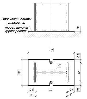
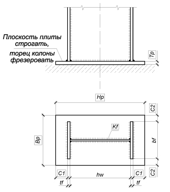
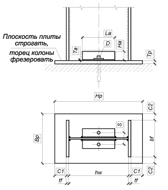
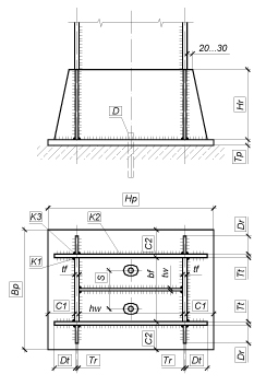
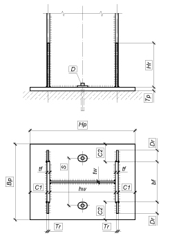
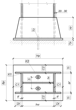
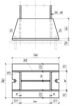
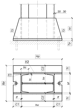
Figure 1. Types of designs for nominally pinned column bases with wing plates and cantilever stiffeners
The Nominally Pinned Column Bases mode enables to design and check the joints of the column bases which provide a pinned column-to-foundation connection. This mode comprises a wide range of designs for this type of joints, such as:
Designs of the nominally pinned column bases provided in the software are somewhat different from those of the rigid column bases. Anchor bolts in these bases are placed taking into account the condition of providing a certain compliance of the joint with respect to the angular deformations, which enables to consider such a column-to-foundation connection as a pinned one.
|
|
|
|
(a) |
(b) |
(c) |
(d) |
|
|
|
|
(e) |
(f) |
(g) |
(h) |
|
|||
(i) (j) (k) |
|||
Figure 1. Types of designs for nominally pinned column bases with wing plates and cantilever stiffeners |
|||
|
|
|
(a) |
(b) |
(c) |
|
||
(d) (e) |
||
Figure 2. Types of designs for nominally pinned column bases without wing plates and cantilever stiffeners |
||
This mode performs the following checks, in compliance with SNiP, SP, DBN:
The Nominally Pinned Column Bases dialog box contains the following tabs: Configuration, Forces, Structure, Welding, Drawing, and Interaction Curves.
First you have to select the type of the column section by clicking the respective button in the Configuration tab. The mode provides four types of cross-sections: a rolled I-section, a welded I-section, a compound section made of two rolled channels, and a circular hollow section. The sizes of the cross-section of the welded I-section and the profile number of the rolled cross-section are specified in the same way as in the Rigid Column Bases mode.
If a compound section made of two rolled channels is selected as the column cross-section type, you then have to select an assortment and the channel number in this assortment in the Select profile dialog box, which can be invoked by clicking the Select the column section button. You can specify the distance between the external faces of the channel webs for such section in the B text field of the Structure tab (for the first type of the base joint). If a circular hollow section is selected as the column cross-section type, its sizes are selected from the respective assortment.
The column cross-section can be checked in the Preview
window, which can be invoked by clicking the Preview
button ( ).
).
Materials used for design and analysis of a nominally pinned column base joint can be selected from the Steel and Concrete drop-down lists, which suggest the steel grades for steel members of the column base joint and concrete classes for the foundation. When a circular hollow section is selected as the column cross-section type, the materials for the nominally pinned base joint can be selected from the following drop-down lists: Steel,Circular hollow section steel and Concrete. A steel grade for the support base plate has to be selected in the Steel drop-down list.
You can enter the service factor for column in the respective text field,
or it can be selected in the Service Factor
dialog box after clicking the nearby button ( ).
).
The service factor of the base plate of the column base is calculated automatically in this mode. The user has to specify the service factor not for the base plate but for the column.
The importance factor which will be further multiplied by the values of all internal forces acting in the column base section has to be specified in the Importance factor field.
The functionality of the Stamp button is the same as that in the Rigid Column Bases mode.
The Welding tab enables to specify
the parameters of the welded connections for the joint. The
Properties of joint contains drop-down lists which are used
to select the type and method of welding, and specify the position of
the weld. This mode implements the following methods of welding in compliance
with Table 34* of SNiP II-23-81* (Table 36 of SP 53-102-2004,
Table 38 of SP 16.13330, Table 1.12.2 of DBN B.2.6-163:2010,
or Table 16.2 of DBN B.2.6-198:2014): manual welding, semiautomatic
welding with solid wire less than 1.4 mm in diameter, automatic and
semiautomatic welding with the electrode wire 1.4 to 2.0 mm in diameter,
automatic welding with the electrode wire 3 to 5 mm in diameter,
and semiautomatic welding with flux-cored wire. The position of weld can
be underhand, flat, horizontal, vertical or overhead. The Properties
of welding materials group displays values of the design resistance
of the fillet welds for conventional shear of the weld metal, Rwf,
and of the characteristic resistance of the weld metal, Rwun.
These values can be specified in the Materials
for Welding dialog box, which is invoked by clicking the button  .
.
 . It
should be noted that when creating an .rsu2
file in SCAD, the table of design
combinations should include only those combinations that correspond to
the section of the bar element adjacent to the node.
. It
should be noted that when creating an .rsu2
file in SCAD, the table of design
combinations should include only those combinations that correspond to
the section of the bar element adjacent to the node.
The Structure tab contains a group of buttons to select a design for the joint of the nominally pinned column base.
To perform a check of the load-bearing capacity of the specified structural design of the column base joint, you have to enter the design parameters of the joint in the table in the Structure tab. The diameter and the steel grade of anchor bolts are selected from the special drop-down lists of the Anchor bolts group. The default units of linear measurement are millimeters.
Clicking the Design button drops down a menu. If the first item, All parameters are not specified, is selected, the automatic selection of all parameters of the joint design is performed and it is assumed that the parameters of the joint design are not specified (are equal to zero), and their previously specified values are ignored. If the Some parameters are specified menu item is selected, the program will automatically determine the values of the undefined (are equal to zero) parameters with fixed values of the specified parameters.
The automatic selection of the nominally pinned column base design was performed on the basis of the analysis of its sensitivity with respect to the variation of the controlled parameters of the joint taking into account the conditions of the adequate resistance and structural constraints defined by the standards (see General Information). The diameter of the anchor bolts and the thickness of the base plate, as well as the dimensions of the support base plate were the controlled parameters.
Clicking the Calculate button will perform the check of the load-bearing capacity of the specified joint members and of the connections between them according to SNiP, SP, or DBN.
After clicking the Design or Calculate button the maximum utilization factor of restrictions (the most dangerous) will be displayed in the Kmax field located in the lower part of the dialog box, and the type of the standard check (strength, stability, local stability, etc.) in which this maximum took place will be indicated, and a drawing of the nominally pinned column base joint design of the MS stage will be generated.
A complete list of the performed checks can be obtained by clicking the Factors button. It will be displayed in the special Factors Diagram dialog box, where you can browse the values of all utilization factors of restrictions. The list of the load-bearing capacity checks of the members and connections of the joints of the nominally pinned column bases performed by the application is given in the table below.
Clicking the Report button generates a report document which contains the initial data and the results of analysis.
Check |
Type of base |
SNiP II-23-81* |
SP 53-102-2004 |
SP 16.13330 |
DBN B.2.6-163:2010 |
DBN B.2.6-198:2014 |
ShNK 2.03.05-13 |
СН КР 53-01:2024 |
|---|---|---|---|---|---|---|---|---|
Bending resistance of the base plate under reduced stresses |
Fig. 2 |
Sec. 5.14*, (33) |
Sec. 9.2.1, (38) |
Sec. 8.2.1, (44) |
Sec. 1.5.2.1, (1.5.4), Sec. 1.7.2, (1.7.1) |
Sec. 9.2.1, (9.4), Sec. 11.2, (11.1) |
Sec. 7.14, (29) |
Sec. 7.14, (29) |
Bending resistance of the base plate under normal stresses in areas supported along the contour |
Fig. 1, a, c, d, e, f |
Sec. 5.12, (28) |
Sec. 9.2.1, (35) |
Sec. 8.6.2, (101), (103) |
Sec. 1.7.2, (1.7.1), Annex N, (N.2), Table N.2 |
Sec.11.2, (11.1), Sec. M, (M.1), (M.2) Table M.2 |
Sec. 7.12, (24) |
Sec. 7.12, (24) |
Bending resistance of the base plate under normal stresses in areas supported on three sides |
Fig. 1, a, b, d, e, f |
Sec. 5.12, (28) |
Sec. 9.2.1, (35) |
Sec. 8.6.2, (101), (104) |
Sec. 1.7.2, (1.7.1), Annex N, (N.2), Table N.2 |
Sec.11.2, (11.1), Sec. M, (M.1), (M.2) Table M.2 |
Sec. 7.12, (24) |
Sec. 7.12, (24) |
Bending resistance of the base plate under normal stresses in areas supported on two sides meeting at an angle |
Fig. 1, a |
Sec. 5.12, (28) |
Sec. 9.2.1, (35) |
Sec. 8.6.2, (101), (104) |
Sec. 1.7.2, (1.7.1), Annex N, (N.2), Table N.2 |
Sec.11.2, (11.1), Sec. M, (M.1), (M.2) Table M.2 |
Sec. 7.12, (24) |
Sec. 7.12, (24) |
Bending resistance of the base plate under normal stresses in cantilever areas of the plate |
Fig. 1, e, f |
Sec. 5.12, (28) |
Sec. 9.2.1, (35) |
Sec. 8.6.2, (101), (102) |
Sec. 1.7.2, (1.7.1), Annex N, (N.1) |
Sec.11.2, (11.1), Sec. M, (M.1), (M.2), Table M.2 |
Sec. 7.12, (24) |
Sec. 7.12, (24) |
Bending resistance of the base plate under normal stresses in free trapezoid areas of the plate |
Fig. 1, a, b, c, d Fig. 2 |
Sec. 5.12, (28) |
Sec. 9.2.1, (35) |
Sec. 8.6.2, (101) |
Sec. 1.7.2, (1.7.1) |
Sec.11.2, (11.1) |
Sec. 7.12, (24) |
Sec. 7.12, (24) |
Resistance of the foundation concrete in local bearing under the plate |
Fig. 1, Fig. 2 |
|||||||
Resistance of the welded connection between the column and the base plate |
Fig. 2, a, b |
Sec. 11.2*, (120)-(121) |
Sec. 15.1.16, (155), (156) |
Sec. 14.1.16, (176), (177) |
Sec. 1.12.1.16, (1.12.2), (1.12.3) |
Sec. 16.1.16, (16.2), (16.3) |
Sec. 13.2, (129)-(130) |
Sec. 13.2, (129)-(130) |
Resistance of the welded connection between the wing plate and column flanges |
Fig. 1, a, c, d, e, f |
Sec. 11.2*, (120)-(121) |
Sec. 15.1.16, (155), (156) |
Sec. 14.1.16, (176), (177) |
Sec. 1.12.1.16, (1.12.2), (1.12.3) |
Sec. 16.1.16, (16.2), (16.3) |
Sec. 13.2, (129)-(130) |
Sec. 13.2, (129)-(130) |
Resistance of the welded connection between the wing plate and the base plate |
Fig. 1, a, c, d, e, f |
Sec. 11.2*, (120)-(121) |
Sec. 15.1.16, (155), (156) |
Sec. 14.1.16, (176), (177) |
Sec. 1.12.1.16, (1.12.2), (1.12.3) |
Sec. 16.1.16, (16.2), (16.3) |
Sec. 13.2, (129)-(130) |
Sec. 13.2, (129)-(130) |
Resistance of the welded connection between the cantilever stiffener and column flanges |
Fig. 1, b |
Sec. 11.4, (33) |
Sec. 15.1.15, (38) |
Sec. 14.1.15, (44) |
Sec. 1.12.1.15, (1.5.4) |
Sec. 16.1.15, (9.4) |
Sec. 13.4 |
Sec. 13.4, (29) |
Resistance of the welded connection between the cantilever stiffener and the wing plate |
Fig. 1, a |
Sec. 11.5, (120)-(123), (126) |
Sec. 15.1.16, (155), (156), Sec. 15.1.17, (157), (158), Sec. 15.1.19, (161) |
Sec. 14.1.16, (176), (177), Sec. 14.1.17, (178), (179), Sec. 14.1.19, (182), (183) |
Sec. 1.12.1.16, (1.12.2), (1.12.3), Sec. 1.12.1.17, (1.12.4), (1.12.5), Sec.1.12.1.19, (1.12.8), (1.12.9) |
Sec. 16.1.16, (16.2), (16.3), Sec. 16.1.17, (16.4), (16.5), Sec. 16.1.19, (16.8), (16.9) |
Sec. 13.5, (129)-(132), (135) |
Sec. 13.5, (129)-(132), (135) |
Resistance of the bolted connection between the anchor angle and the base plate |
Fig. 2, c |
Sec. 11.7*, (127)-(128), Sec. 11.8, (130) |
Sec. 15.2.9, (167), Sec. 15.2.10, (168) |
Sec. 14.2.9, (186), (187), Sec. 14.2.10, (189) |
Sec. 1.12.2.9, (1.12.12), (1.12.13), Sec. 1.12.2.10, (1.12.15) |
Sec. 16.2.9, (16.12), (16.13), Sec. 16.2.10, (16.15) |
Sec. 13.7, (136)-(137), Sec. 13.8, (139) |
Sec. 13.7, (136)-(137), Sec. 13.8, (139) |
Notes: see the table in the Rigid Column Bases section. |
||||||||
Once you switch to the Drawing tab, the application performs a check of the load-bearing capacity of the nominally pinned base joint similarly to the Calculate mode. If the results of analysis of the parameters of the joint members do not contradict the structural and standard requirements, a drawing of the nominally pinned base joint design of the MS stage will be generated.
The functionality of the Report button and of the controls in the Drawing tab is similar to that described for the Rigid Column Bases mode.
The curves enclosing an area of the load-bearing capacity of the specified (or selected) design of the nominally pinned column base joint under various pairs of internal forces which can arise in the column base section are plotted in the Interaction Curves tab.
Click the Show button to generate such a curve. A drop-down list serves to select a pair of variable internal forces, and all other forces are taken as values specified in the Fixed values group.
Using your mouse pointer, you can explore the area of the load-bearing capacity of the nominally pinned base joint shown in the graph. Every position of the pointer corresponds to a pair of numerical values of the variable forces; their values are displayed in the respective fields. Clicking the right mouse button will display the list of performed checks and values of the factors for the set of forces corresponding to the current position of the pointer in the plot area of the interaction curve.
The maximum value of the utilization factor of restrictions Kmax,
that corresponds to the current values of the internal forces will be
displayed in the Factor field,
and the name of the type of check in which it takes place will be output
in the Critical factor field.
When the pointer is placed outside the area of the load-bearing capacity
where Kmax > 1,
a warning sign is displayed next to the name of the type of check .
The dialog box also contains three buttons: 

 , which enable to perform the following operations:
— if the
forces are specified, clicking this button will draw the points the coordinates
of which in the area of the load-bearing capacity correspond to these
forces;
— drawing
a convex hull of the points specified above, i.e. an entire set of points
which may result from a linear combination of specified forces, including
their incomplete values;
— saving the
forces that can lead to Kmax=1
in a text file (this file can be imported into other programs for further
analysis).